This thread has been locked.

If you have a related question, please click the "Ask a related question" button in the top right corner. The newly created question will be automatically linked to this question.

LP876242Q1EVM: How to config the Watchdog to enable the nRESET output on GPIO10 for SOC reset ?

Part Number: LP876242Q1EVM
Other Parts Discussed in Thread: AM2732

Hi ,

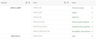
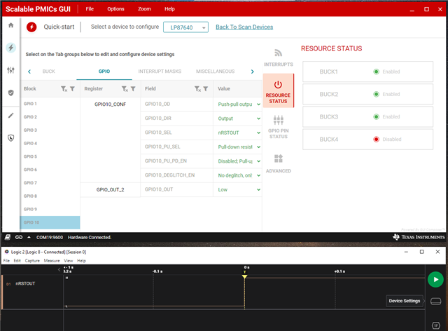
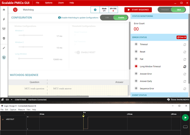
I want to use LP876242Q1EVM(BMC085A) to a generate a nRESET signal for the external system .

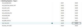
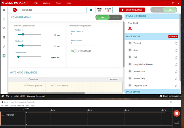
By enabling or disabling the watchdog, a reset signal can be generated to trigger an external system to reset.

Can you pls guide me how to config the watchdog for that purpose?


Thanks,
Simon

  • Hi Simon,

    Let me get back to you by today after consulting with expert of the device. 

    Br,

    Ishtiaque 

  • Hi Simon,

    First of all it depends on which watchdog mode is selected ( Trigger mode or Q&A) , you could read that in section 7.3.8 of datasheet. For now let's assume that it is trigger mode. So , in this mode, MCU applies a pulse signal on the pre-assigned GPIO input pin ( which is configurable by TRIG_WDOG  function)  to send the required watchdog trigger. 

    From section 7.3.8.1 of data sheet, now in case of failure ( which means watchdog is not feeding correctly) there two following conditions based on which actions will be taken by the PMIC.

    1. If the WD_FAIL_CNT (WD failure counter) is only greater than WD_FAIL_TH ( Configurable Fail Threshold),

    • The device clears the ENABLE_DRV bit   (Alternative programmable function configurable to GPIO1 pin: EN_DRV - Enable Drive output pin to indicate the device entering safe state (set low when ENABLE_DRV bit is '0') 
    • Sets the error-flag
    • Pulls the nINT pin low. 

    2.  If the WD_FAIL_CNT is greater than WD_FAIL_TH + WD_RST_TH (configurable reset threshold), provided watchdog-reset function is enabled (configuration bit WD_RST_EN=1). 

    • Device generates WD_ERROR trigger in the state machine.  This WD_ERROR trigger in state machine causes the reset during which the GPIO pin assigned  as nRSTOUT or NRSTOUT_SoC are pulled low depending on the configuration ( So here, GPIO10 can be configured as nRSTOUT_SOC)
    • Sets error-flag
    • Pulls the nINT pin low

    GPIO10 Configuration, see Table 5-1 and Table 7-59 in the data sheet.

    Best regards,

    Ishtiaque Panhwar

  • Hi Simon,

    The above mentioned description gives the general description of how it should be. However, after consulting with device expert, the specific answer to your question is following. 

    In LP876242Q1EVM, if the PMIC populated is LP876242B0RQKRQ1 with  TI_NVM_ID=0xe0 and TI_NVM_REV=0x2 (please confirm me that), then WD_ERROR trigger  causes the warm reset and GPIO10 which is configured as nRSTOUT is pulled low. In this NVM, GPIO10 is not configured as nRSTOUT_SoC. So, if  you can use the nRSTOUT pin for the SoC reset that can be done. However, you cannot configure that through SPI writes.

    Best regards,

    Ishtiaque

  • Hi Ishtiaque ,

    Yes , in the register map NVM_CODE_1(TI_NVM_ID) = 0xE0 and NVM_CODE_2(TI_NVM_REV) = 0x00 .
    However ,I'm a little bit confused what do you mean I can't configure that through SPI ?

    As you mentioned above , I can do the flow steps after power up the EVM :
    step1 : configure GPIO10 as nRSTOUT,GPIO10_PU_SEL = Pull-up, GPIO10_OUT = High


    step2 : configure WatchDog Registers - Page 4
    WD_WIN1_CFG = 0x00 (80ms,as short as we can to generate a nRSTOUT)
    WD_WIN2_CFG = 0x00 (80ms)
    WD_LONGWIN_CFG = 0x00 (80ms)

    step3 : WD_EN =1 then I can capture seveal nRSTOUT pulses and GPIO10 stay in LOW .

    But this is one time configuraton, I can't get another nRSTOUT signal without repower on the PMIC and flow the above steps.Can you help me with this issues?

    Thanks,
    Simon

  • Hi Simon,

    Thank you for information.

    So it is the older version of device on the EVM. I will get back to you on Monday after going through that configuration and more clear instructions.

    Best regards,

    Ishtiaque Panhwar 

  • Hi Simon ,

    If you are configuring through GUI then should be having following interface after successfully powering on the PMIC.

    Then in watchdog evaluation window, you configure settings of window-1 and 2 to be less than 31ms and at the same time you could see below signal that that nRSTOUT is high. Here ENABLE RESET is enabled as well. And here WD is Q&A type configured. 


    After this now I am enabling the WD but not starting the sequence. so you could see the first reset of nRSTOUT which is captured and after 7 resets the nRSTOUT goes low. So nRSTOUT can be configured as system reset. 


    But, I would like to know what is it that you trying to get from this kind of test. or in other words on high level what do you want to do. Can you me that information so I might be able to support you from that perspective. However, following above steps would answer to your query regarding WD configuration to toggle nRSTOUT as a system reset. 

  • Hi Ishtiaque Panhwar ,

    I need to test AM2732 mcu system with diferent configurations.so it's nessary to use nRST signal rather than the warm reset signal to completely reset the entire system.

    Best regards,

    Simon.

  • Hi Simon,

    It is unclear to me that what do you want to test with AM2732 MCU. 

    If you just want to give a reset pulse then you can do with same nRST signal by enabling the WD and let the WD long window get timed out once. This would toggle the nRST signal and that can be used to give reset to MCU. After wards, you can maintain the WD sequence by feeding it again during the WD long window before it gets expire. 

    Best regards,

    Ishtiaque Panhwar

  • Hi Ishtiaque Panhwar ,

    It's clear to me now .Thank you for your kind help.

    Best regards,

    Simon