This thread has been locked.

If you have a related question, please click the "Ask a related question" button in the top right corner. The newly created question will be automatically linked to this question.

TUSB546A-DCI: mux with TUSB546A, MCU, TPS65988 I2C

Part Number: TUSB546A-DCI
Other Parts Discussed in Thread: TPS65988,

Hi, I want to program TUSB546A using MCU. MCU will be a bridge between TPS65988 PD Controller, TUSB546A. I do not fully understand which register I must read from PD controller.

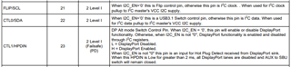
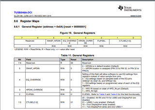
What I understand that I can mux configuring CTLSEL1, CTLSEL0 and FLIPSEL registers in TPS546A side.

I did not understand that What does CTLSEL1, CTLSEL0, FLIPSEL represent in PD controller side.

I want to use 2 dp lane and USB3.1 in my processing device and in other device I want to use only USB3.1.

  • Hi,

    CTL0, CTL1, and FLIP will be connected to GPIOs on the PD controller.

    GPIO mapped to cable orientation event will connect to FLIP.

    GPIO mapped to USB3 event will connect to CTL0.

    GPIO mapped to DP mode select event will connect to CTL1.

    You can refer to Figure 2 in this document on how to setup the GPIO

    Regards

  • I do not want to use gpio of pd controller because pd controller is on other module. I want to use I2C and control tusb546a using mcu. Please do not share unrelated solution

  • Hi,

    If that's the case you can read register 0x5F and look for the DPConnection, USB3Connection, and DataOrientation bit. These information can be found in the TPS65988 Technical Reference Manual.

    Please note that there is a enumeration timer for USB3 bus powered device and using a MCU reading the PD controller data status then configuring TUSB546A-DCI might exceed the timer and downgrade the speed to USB2. If you have any question regarding this I can transfer this to the redriver team.

    Regards

  • There is a table that 3-79. It shows that dpsourcesink register need to be readed. 

    What does this table says? I am a bit confused.

    I create VESA pin assingment E, F, C, D, A.

    DataOrientation or cable orientation which one is proper for configurating?

    uint8_t tps65988_mux_data(tps65988_t *tps65988) { uint8_t PlugOrientation = tps65988_get_PlugOrientation(tps65988); uint8_t DPConnection = tps65988_get_DPConnection(tps65988); uint8_t USB3Connection = tps65988_get_USB3Connection(tps65988); uint8_t DPPinAssignment = tps65988_get_DPPinAssignment(tps65988); uint8_t DPSourceSink = tps65988_get_DPSourceSink(tps65988); if (DPConnection == 0 && USB3Connection == 1) { switch (PlugOrientation) { case 0: return USB_NORMAL; break; case 1: return USB_FLIPPED; break; } } else if (DPConnection == 1) { switch (DPPinAssignment) { case 0: if (USB3Connection == 0) { if (PlugOrientation == 0) { return DFP_D_PIN_ASSIGNMENT_E_NORMAL; break; } else if (PlugOrientation == 1) { return DFP_D_PIN_ASSIGNMENT_E_FLIPPED; break; } } else if (USB3Connection == 1) { if (DPSourceSink == 0) { if (PlugOrientation == 0) { return DFP_D_PIN_ASSIGNMENT_F_NORMAL; break; } else if (PlugOrientation == 1) { return DFP_D_PIN_ASSIGNMENT_F_FLIPPED; break; } } if (DPSourceSink == 1) { if (PlugOrientation == 0) { return invalid_value; break; } else if (PlugOrientation == 1) { return invalid_value; break; } } } case 1: if (PlugOrientation == 0) { return DFP_D_PIN_ASSIGNMENT_C_NORMAL; break; } else if (PlugOrientation == 1) { return DFP_D_PIN_ASSIGNMENT_C_FLIPPED; break; } case 2: if (PlugOrientation == 0) { return DFP_D_PIN_ASSIGNMENT_A_NORMAL; break; } else if (PlugOrientation == 1) { return DFP_D_PIN_ASSIGNMENT_A_FLIPPED; break; } case 3: if (PlugOrientation == 0) { return invalid_value; break; } else if (PlugOrientation == 1) { return invalid_value; break; } } } }

  • Hi,

    There seems to be a typo in the TRM. Bit 1 should be the cable orientation you need to read.

    Table 3-79 is a truth table for DPPinAssignment, USB3Connection, DPSourceSink.

    The information required to configure the redriver is in register 0x5F. If you have any other question regarding TUSB546A-DCI I can transfer this to the redriver team.

    Regards

  • Is my code enough for redriver If I add cable orientation? I read DPSourceSink, USB3Connection,  DPPinAssignment and orientation and create mode for redriver.

    uint8_t tps65988_mux_data(tps65988_t *tps65988) { uint8_t PlugOrientation = tps65988_get_PlugOrientation(tps65988); uint8_t DPConnection = tps65988_get_DPConnection(tps65988); uint8_t USB3Connection = tps65988_get_USB3Connection(tps65988); uint8_t DPPinAssignment = tps65988_get_DPPinAssignment(tps65988); uint8_t DPSourceSink = tps65988_get_DPSourceSink(tps65988); if (DPConnection == 0 && USB3Connection == 1) { switch (PlugOrientation) { case 0: return USB_NORMAL; break; case 1: return USB_FLIPPED; break; } } else if (DPConnection == 1) { switch (DPPinAssignment) { case 0: if (USB3Connection == 0) { if (PlugOrientation == 0) { return DFP_D_PIN_ASSIGNMENT_E_NORMAL; break; } else if (PlugOrientation == 1) { return DFP_D_PIN_ASSIGNMENT_E_FLIPPED; break; } } else if (USB3Connection == 1) { if (DPSourceSink == 0) { if (PlugOrientation == 0) { return DFP_D_PIN_ASSIGNMENT_F_NORMAL; break; } else if (PlugOrientation == 1) { return DFP_D_PIN_ASSIGNMENT_F_FLIPPED; break; } } if (DPSourceSink == 1) { if (PlugOrientation == 0) { return invalid_value; break; } else if (PlugOrientation == 1) { return invalid_value; break; } } } case 1: if (PlugOrientation == 0) { return DFP_D_PIN_ASSIGNMENT_C_NORMAL; break; } else if (PlugOrientation == 1) { return DFP_D_PIN_ASSIGNMENT_C_FLIPPED; break; } case 2: if (PlugOrientation == 0) { return DFP_D_PIN_ASSIGNMENT_A_NORMAL; break; } else if (PlugOrientation == 1) { return DFP_D_PIN_ASSIGNMENT_A_FLIPPED; break; } case 3: if (PlugOrientation == 0) { return invalid_value; break; } else if (PlugOrientation == 1) { return invalid_value; break; } } } }

  • Hi,

    I will transfer this to the redriver team so they can comment on your code.

    Regards.

  • Hi,

    Besides  DPSourceSink, USB3Connection,  DPPinAssignment and orientation and create mode for redriver, you would want to set the following TUSB546 registers/bits

    1. Register 0x0A, bit 4 -> Enable EQ settings based on programmed value of each of the EQ registers

    2. Register 0x10 and 0x11 -> EQ setting for DP lane

    3. Register 0x20 and 0x21 -. EQ setting for USB transmitting and receiving

    You may also write a value of 0x80 to register 0x13 to disable AUX snooping if you don't care the TUSB546 power consumption.

    Thanks

    David

  • You misunderstand, my code is in pd controller for creating mode data to send to TUSB546. I did all of you said in TUSB546 side. My problem is that how to create data in PD controller side.

  • Hi,

    We do not allow user inserting their own code into our PD controller. You can run your code in the MCU and read the Data Status Registers.

    I am not understanding what you meant by "how to create data in PD controller side." 

    Regards

  • I meant that my pd controller is on other module. I want to read data status register using mcu and transmit data to other module(my usb mux module). I know what to do in mux side that TUSB546A. I asked you what bits I must read from PD controller and must transmit to USB mux module.  I did not understand that What does CTLSEL1, CTLSEL0, FLIPSEL represent in PD controller side.

  • Hi,

    Please see the TUSB datasheet below on bit definition. You can see the FLIPSEL is equivalent to the FLIP pin connection which correspond to cable orientation in the PD controller register 0x5F, CTLSEL0 is equivalent to CTL0 pin connection which correspond to USB3Connection in the PD controller register 0x5F, CTLSEL1 is equivalent to CTL1 pin connection which correspond to DPConnection in the PD controller register 0x5F.

    Regards