This thread has been locked.

If you have a related question, please click the "Ask a related question" button in the top right corner. The newly created question will be automatically linked to this question.

TPS62872-Q1: TPS62872-Q1

Part Number: TPS62872-Q1
Other Parts Discussed in Thread: TPS62872

Background:

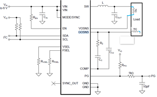
From TPS62872 datasheet, it is suggested that connect the COMP pins of all stacked devices together and connect a resistor and capacitor between the common COMP node and GOSNS, but has no statement show that GOSNS must be connected to GND, just a diagram showing the compensation network is connect to GND of load.  

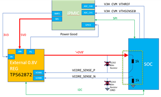
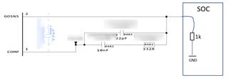
In our design as below diagram, we could see resistance inside the  load for GOSNS and VOSNS.

  1. Resistance between output voltage to VOSNS is ~1Kohm
  2. Resistance between GOSNS to GND is ~1Kohm


Note: the load in this picture is a SOC and the connected two pins are two dedicated pins for remote to sense.

So the question is:

        1. If GOSNS must be connected to the GND directly? if there can be a series resistor, what's the maximum impedance?

        2. If the compensation circuit (from COMP) must be connected to GOSNS? or can it be connected to GND directly or it can be floating?

        3. In our circuit diagram, GOSNS is connected to the GND via a 1K resistor. and the compensation network is then connected to GOSNS. So can the compensation network work normally in our design?

Thank you and look forward to the reply.

Block diagram:

  • Hi,

    COMP pin shouldn't be floating. It should connected to GOSNS pin of device. Remote sensing connection should have lower impendence path and to get stable regulation.

    you can take EVM layout as reference on board.  https://www.ti.com/tool/TPS62873EVM-143

    Do you have 1kohm internal on SOC , can you share more detail ? you can connect the Remote sense to capacitor connected near to load. 

    Best regards,

    Tanvee

  • Hi Tanvee,

    Sorry, I check the questions and find mistakes, the question I need to reshape as below:

    For question 1, I need to confirm if GOSNS must be used and connected to GND? can it be floating?

    For question 2, I understand you mean the compensation network should be connected to GOSNS.

    And let me further explain the issue happens in our project:

    The circuit diagram is shown as below and there is an oscillation in VCORE_SENSE_N during the power startup.

    And we find that there are two 1kohm resistors inside the SOC.

    So I ask this question to make clear what's the design requirement from TI and to verify if we have a incorrect design.

  • Hi ,

    Thnaks for sharing details.

    Yes, you have to connect GOSNS pin to SOC ground and don't keep it floating or don't connect to power ground of the PCB.

    Sense lines are quite sensitive and high chances that connections made for sense line is causing he oscillation. Can you share layout, schematic and oscillation waveforms? It can help to reach out to root cause.

    Best regards,

    Tanvee 

  • Hi,

    Below 1st picture is an oscillation picture in our test, and the 2nd picture shows the current focus point on root cause analysis that there is the 1kohm inside SOC (but nevertheless this 1k is judged after a measurement and not confirmed by the SOC supplier now).

    In additional, we have checked the layout of remote sensing signals without obvious finding on noise path.

    And basing on the requirement of TI (GOSNS to GND), I think 1K issue is most possible the root cause.

  • Hi,

    I would agree with your comment here. GOSNS pin should not connect with 1kOhm resistor. There is current flowing from this signal and with additional resistor will change the voltage regulation. This is might be root cause for oscillation here.

    Can you share layout and measurement set up? 

    Best regards,

    Tanvee

  • Hi,

    I am closing thread as discussion is ongoing offline.

    Best regards,

    Tanvee