This thread has been locked.

If you have a related question, please click the "Ask a related question" button in the top right corner. The newly created question will be automatically linked to this question.

TPS1H200A-Q1: Why is the TPS1H200A-Q1's Fault signal being triggered

Part Number: TPS1H200A-Q1

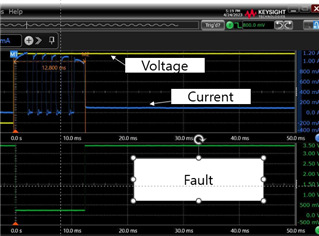
Why does the Fault signal occur when the current swings as shown in the above result for the TPS1H200A-Q1 IC?

Is it because of current limit exceed due to inrush current?

There is no information in the datasheet. What could be the possible symptom

  • Hi Joung,

    This is thermal swing caused due to the current limit. It is expected behavior of the device to output a fault signal here.

    Please look at Figure 7-11 in the datasheet for a good representation and Table 7-2 for a quick reference on all the faults reported by the device.

    Thanks,

    Shreyas

  • Thank you for answer. However, I do have a few questions.

    You said in your answer that it was thermal swing due to current limiting.
    Our circuit is designed to operate in latch off mode when overcurrent is cut off.

    The waveform shows a thermal swing fault situation,
    The output appears to have been restored automatically when fAULT is disabled.

    So what is the difference between a thermal swing fault condition and an overcurrent shutdown fault condition?
    (I wonder why the waveform can be interpreted as thermal swing and not current limiting?)

  • Hi Joung,

    Current limiting is a thermal event. This is because the current limit causes high power dissipation across the device which heats it up. The turn off event is caused due to the junction hitting thermal shutdown. The device then turns off and if latch is engaged, it does not retry.

    Thermal swing is an interim condition that occurs when the FET rises in temperature faster than the control structure. This avoids the situation of hotspots in the device. The device automatically turns off and on based on thermal rise of the FET that can occur during high power limiting events. 

    Thanks,

    Shreyas

  • Thank you for your response.

    I have a question regarding the temperature test conducted on the product.

    When the temperature chamber was set to 50 degrees, there were no fault signals and the output was fine.

    However, when the chamber temperature was set to 60 degrees, both the fault signal and output were absent.

    (When the switch was turned on at 60 degrees or higher, the output did not work and a Fault signal occurred continuously.)

    Is this symptom related to thermal swing?

    Also, the IC's temperature guarantee is known to be 125 degrees,

    so why doesn't the output work at a chamber temperature of 60 degrees?

    Could this symptom be related to thermal swing?

    Does thermal swing occur when the temperature condition exceeds 60 degrees and the current limit is exceeded?

    I am urgently investigating the cause related to the product. I would really appreciate a quick response.

    Thank you.

  • Hi Joung,

    The power dissipation is calculated as (Tj-Ta)/R,t,j,a. During turn on, if the current limit is hit, the power dissipation is V*I across the device. Please note that a current limit event is a thermal event.

    If your ambient temperature is higher, it is possible that you are hitting absolute thermal shutdown which causes the device to turn off. Junction temperature and ambient temperature are different from each other as there is a power loss in the device as current flows through it. Thermal swing occurs when the FET is hotter than the controller within the device. I suspect that in your test case, you are seeing thermal shutdown.

    From the presented explanation, the device is behaving as expected. Please refer to the section 7.3.5.4 for more information in the datasheet.

    Thanks,

    Shreyas

  • I now have a complete understanding of IC, thanks to you.

    I apologize, but I have one last question.

    The Inrush current of the system in use through the IC is around 5A. (The duration is about 10-20ms.),

    and the power consumption after boot is about 650mA.

    Currently, the current limit of the switch is set to 2A, including a margin for the normal operating current.

    As I mentioned in my previous question, boot failure occurs when the temperature exceeds 65 degrees,

    which is likely due to thermal shutdown or thermal swing caused by the current limit during the inrush current period.

    (Based on the fact that the state has not recovered, we suspect Thermal Shutdown as the cause)

    Is it the correct choice to set the current limit to 2A in this situation?

    To ensure the operation of the switch at high temperatures, should the current limit be set considering the initial inrush current?

    (I know that the guaranteed current of TPS is Max 4.8A.)

    I'm sorry to bother you, but could you please answer my question again? Thank you so much.

  • Hi Joung,

    When the current limit is low, the inrush event will cause the device to hit the limit. This will cause the device to operate in a saturation mode which causes higher power dissipation causing turn off in some situations as you have found.

    The options that you have include decreasing the current limit to a lower amount causing longer turn on but less power dissipation or to improve the heatsinking capabilities of the device. Another option is to reduce the downstream capacitance to reduce the amount of inrush current expected.

    Thanks,

    Shreyas