

Other Parts Discussed in Thread: BQ24115, BQ24171, , BQ24125, BQ24172
A block diagram of the BQ24171, BQ24172, BQ24105, BQ24115, BQ24125 connection to the battery is shown below:
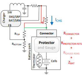
The charge current flowing across the resistances and impedance, shown in red and grouped as RTOTAL, induce an undesirable voltage drop that adds to the battery pack cell(s) voltage. The charger enters constant voltage (CV) mode when the voltage at its sense point, RTOP above, reaches VBATREG. The charge current begins to taper down the termination current, ITERM. The voltage sense point should be connected, as shown in green, as close to the battery connector as possible to eliminate the effect of PCB trace resistance, and therefore reduce taper time.
The issue is simplified to show only 3 pulses before final termination in the diagram below
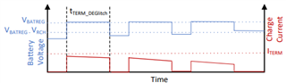
where VBATREG is the charger's battery regulation voltage, VRCH is the battery voltage drop required for a recharge cycle to start and ITERM is the termination current setting.
The VRCH threshold for BQ24171, BQ24172, BQ24105, BQ24115 and BQ24125 is 50mV x (1+RTOP/RBOTTOM). If ITERM x RTOTAL>VRCH, the charger repeatedly terminates, enters recharge and terminates until the battery cells finally charge high enough. This type of pulse charging is generally not a problem for the battery or the charger. However, it can be eliminated. If reducing RTOTAL is not an option, the next option is to reduce the termination current. For the BQ24105, BQ24115 and BQ24125, the ISET2 resistor sets precharge and termination currents. For BQ24171 and BQ24172, ITERM is a percentage of charge current set by the ISET pin resistor. Therefore a NFET with source at ground plus series resistor in parallel with the bottom ISET is one option to reduce the charge and termination current. The gate of the NFET can be driven by a voltage divider sensing the battery voltage.