This thread has been locked.

If you have a related question, please click the "Ask a related question" button in the top right corner. The newly created question will be automatically linked to this question.

TPSM8D6C24: Remote sensing

Part Number: TPSM8D6C24

Hi, 

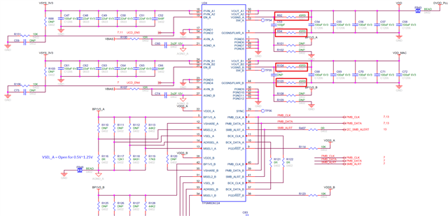
We use TPSM8D6C24 as PMIC and place remote sesing on loading side, the resistor is 49.9R based on TPSM8D6C24EVM reference design.

Is it possible to increase or decrease the remote sensing function effect by modify the resistor value?

Thanks.

  •  

    The TPSM8D6C24 does not have an internal VOUT sense path, so you would need a second VOUT to VOSNS path with it's own resistors to mix local and remote sensing.  If you have multiple resistive paths between the output voltage and the VOSNS input, the TPSM8D6C24 will regulate to the average voltage between the multiple sense points and the relative resistor values will set the average weighting, with greater weight given to the paths with lower series resistors.

    If you are sensing the output voltage after the ferrite bead, I would recommend having a capacitive path from the local VOUT close to the TPSM8D6C24 to VOSNS so that the feedback sense point can favor the local VOUT at high frequencies and the remote VOUT at low frequencies in order to avoid issues with delays induced by the ferrite bead and any capacitance located after it.

  • Hi Peter,

    In our case, VOUT = VDD (we don't care DVDD_PLL after the ferrite bead because it's lower loading) and we have only one resistor on loading side on our PCB.

    Based on your explanation, we can't change the sensing effect by lower/higher resistors on current schematic.

    We should modify our schematic to add multiple resistive path to average weighting.

    Is it right?

  •  

    No, with the current schematic you can not change the remote sensing effect with higher or lower resistance on the current schematic, but the current schematic shows direct sensing of the immediate output voltage of the converter, so I am not sure I understand the question.  Perhaps if you describe your situation more, I can understand what you are trying to do and better advise you.

    1) Is the output VDD routed a long distance from the TPSM8D6C24 to the consumer of VDD?

    2) Are there multiple consumers of VDD?

    3) Are you seeing an issue with the current design that you are trying to address by changing the remote sensing effect / weighting?