


Hi Expert,
I am posting in order to understand an issue we had in the past when assembling our battery pack. Our design follows the attached simplified schematic (dismiss the blue line for now - I'll explain later). What we were finding is that during the assembly process, the cells would get soldered incrementally starting with cell 0 and going up to cell 15. The assembly process would also happen in under 60 seconds. For about 10% of our batteries, we were finding that the charge pump would have some internal failures and not function correctly after assembly. In order to fix this issue, we connected cell 15 to PACK+ (as shown with the blue line) during the assembly process of soldering cells 0 to 15. I am wondering if you can provide any details why this failure existed and how shorting cell 15 to PACK+ prevented the charge pump from exceeding a maximum voltage rate or internal failure?
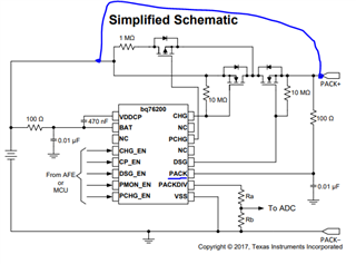
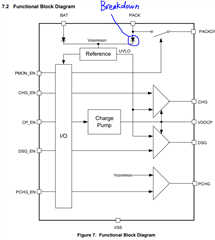
One theory I have is the diode circled in the functional block diagram below is exceeding the reverse breakdown voltage or the PACK pin is exceeding its max rating. I have this theory because during the battery assembly process (before adding in the blue line above), the cells get soldered starting with Cell 0 and incrementally goes up to Cell 15. When I monitor the voltage of the PACK pin during this assembly process, I see that PACK pin begins at 0V and incrementally increasing by the cell voltages. After Cell 14 is connected, the PACK pin reaches 48V. After the final Cell 15 is connected, the voltage on PACK pin goes down to 0V. I can understand that including the blue connection shown in the simplified schematic above adds a more stable voltage on the PACK pin and somehow prevents the breakdown voltage of the diode from exceeding or exceeding some max rating of the PACK pin. Do you know why else we might have been seeing this failure? What is the reverse breakdown voltage of this diode?
Thanks,
Joe
