Other Parts Discussed in Thread: LMR54410
Powersupply_schematic_for_review.pdf
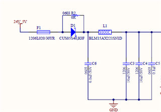
We are designing our product using TPS55165-Q1 and LMR54410FDBVR to obtain the output as 5V, 0.5 A and 3.3V,0.5 A respectively. Please find the schematic attached for your reference.
Kindly request you to review and provide your valuable feedback.
Please help us with following queries as well :
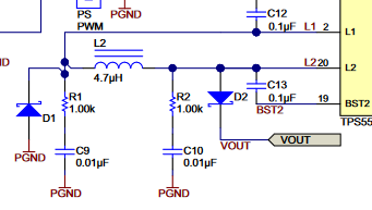
- As we can see in the TPS55165-Q1 EVK schematic the inductor has diodes(D1 and D2) at either ends. Should we need to include in our design? Kindly please us to understand the purpose.
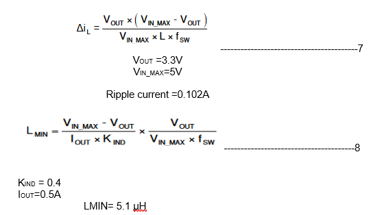
- Inductor value calculated with mentioned formula in the datasheet of LMR54410FDBVR is around 5.1 uH, when we simulate the with same input parameters we are getting it around 2.7 uH in the TI web bench. Please help us to choose the right value.We are using Ferrite bead at the input , will it be okay. The current design the is for 0.5A, 5V and 0.5A/ 3.
- We are usimg ferrite bead at the input of Buck,is it fine