This thread has been locked.

If you have a related question, please click the "Ask a related question" button in the top right corner. The newly created question will be automatically linked to this question.

UCC256301: Best Controller for 100 kHz, 100W LLC?

Part Number: UCC256301

I need a pure sine, soft-switched resonant constant-voltage DC/AC inverter, operating at 100 kHz, up to 20A @ 5V. 

The load is inductive: several parallel coupled-inductors for galvanic isolation. 

There should be a simple feedback loop to set constant voltage from 0V to 5V (i believe that's typically done by increasing the switching freq such that it's attenuated by the resonant circuit). 

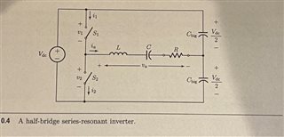
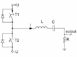
It should be a half-bridge or quarter-bridge design. 

Seeking a lowest-parts-count solution. 

Thx!

  • Hi:

      For a DC-AC converter based on resonant converter, a LLC similar DC-rectified AC stage can be used, then a constant switching frequency based modulation strategy can be considered to generate sinusoidal output voltage generally. So, this is not a simply general LLC solution can be achieved, especially for the TI Analog LLC solution.

      Especially, It is still with some challenge to produce a 100KHz 5VAC's output.  so, we are hard to propose such a lowest-part-count solution with analog solution. 


  • Hello, 

    I don't understand your answer. 

    What do you mean " DC-rectified AC stage"? Why would we need a rectifier to produce AC?

    I want to build the circled block:


    An introduction to LLC resonant half-bridge converter (st.com)

    Here are some example resonant inverters:

    In our application, there will be a DC input @ 12V to 24V. The inverter will convert that to 5V AC.

    Are you saying TI parts cannot support a resonant inverter @ 100 kHz?

    So, i cannot build a resonant inverter with TI parts? Really???

    Can you recommend a different IC manufacturer? How about NXP, Infineon, or ST Micro?

    Thx

  • Hi Johny,

    I think your question was misunderstood. All of our LLC controllers work as you describe above to convert a DC input into a square wave followed by a resonant tank to make a sine wave on the primary side of the transformer. The LLC transfers the stored energy across the isolation barrier which then gets rectified as a DC voltage. Our best controller for this is the UCC25640x series. 

    I hope this answers your question.

  • Thanks. For my application, i don't require a DC output, so i don't need rectification. 

    Would the UCC25640x work for that?

    This controller datasheet states:

    The transformer can be built or purchased according to these specifications:
    • Turns ratio: Primary : Secondary : Bias = 33 : 2 : 3
    • Primary terminal voltage: 450 Vac

    But my input voltage is 12V to 24V DC. And my preferred OTS coupled inductors are 1:1. 

    So i don't think this part will work for our application. 

    Correct?

  • Hi Johny,

    The UCC25640x assumes a PFC front-end but that is not always required. Especially when your input is DC.  For 12V in, you would need an auxiliary supply as the minimum input voltage is 13V.

    I have not seen an LLC used without a rectification stage on the secondary side. I will have to check with others to get their thoughts on this.

  • Aren't there plenty of resonant inverters on the market, with AC output? I see many "quasi-resonant" inverters for sale on Amazon, but not sure if that's relevant. 

    When would a PFC input not be required?

    An additional DC/DC converter at the input wouldn't be terrible, but we prefer a controller that works with 12V in. 

    Thanks.

  • Hi Johny,

    Could you clarify following questions?

    1.

    There should be a simple feedback loop to set constant voltage from 0V to 5V

     How do you set the reference voltage for 0V?

    2. Usually, the resonant capacitor of the LLC should be ground referenced to get the resonant voltage and resonant current information which is required by the UCC256x0x family of devices. So, is it okay for your application? 

    Let me know.

    Regards

    Manikanta P

  •  How do you set the reference voltage for 0V?

    Why do i need a reference voltage? I thought Vout of a resonant inverter is set by adjusting the frequency of the input oscillator. 

    Are you saying that your controller IC only requires a reference voltage, and the IC will intelligently adjust oscillator frequency so Vout matches Vref?

    In that case, Vref would be a reference voltage set to my desired output voltage. It could be a reference voltage IC. There could be some logic, external to the resonant inverter, which outputs a desired reference voltage. 

    It will be ground-referenced to the resonator side of the load-trafo (primary). 

    Does that help?

     the resonant capacitor of the LLC should be ground referenced to get the resonant voltage and resonant current information which is required by the UCC256x0x family of devices. So, is it okay for your application? 

    Ground on the primary side of my load-transformer?

    It's ok, as long as this connection doesn't prevent galvanic isolation between primary and secondary of my load-transformer. 

    Can you share a schematic?

    Specs

    Here's a restatement of my specs:

    I need to make a Resonant Inverter, with AC output.

    • application is an AC power supply
    • Topology: LLC or other
    • Input: 12V to 24V DC
    • Output: 0V to 5V AC
    • No DC output, no rectification
    • 100 kHz
    • 100W
    • constant voltage
    • Output: 0 to 5V
    • Output: 0 to 20A continuous
    • Inductive load for galvanic isolation. 
    • pure sine
    • soft-switched
    • 1/2 bridge or 1/4 bridge
    • Powers a mobile consumer device, so form factor is small and light.

    Our load uses AC directly from the secondary of the load-trafo. We will not rectify or filter the secondaries of the load-inductor. 

  • Hi,

    You cannot use this controller for controlling the AC output voltage as the Feedback current variation needs to be linear for this controller.  Also, you need to be able to generate the AC reference voltage (for comparing with the actual output voltage) from the chip that generates DC reference voltage in order to generate the feedback signal. 

    You cannot have 0V as reference as LLC output. OV output can only be achieved by turning off the controller pulses completely by disabling the controller.

    Regards

    Manikanta P 

  • the Feedback current variation needs to be linear for this controller. 

    Can you explain that? I don't understand the problem. 

    Is the following fine?

    Vref would be a reference voltage set to my desired output voltage. It could be a reference voltage IC. There could be some logic, external to the resonant inverter, which outputs a desired reference voltage. 
  • Hi,

    The current that is pulled out FB pin in case of the actual LLC topology + rectifier will be very small during steady state. 

    But in your case, since the AC voltage is being controlled here, the variation of FB current will be very high, Also, the implementation of a compensator in order to control the AC voltage is not Stright forward.

    Vref would be a reference voltage set to my desired output voltage. It could be a reference voltage IC. There could be some logic, external to the resonant inverter, which outputs a desired reference voltage. 

    Since the AC voltage is being controlled, you need to generate the sinusoidal reference voltage. You cannot use DC refence voltage as reference signal in this case.

    I would recommend using digital controller for this application where AC can be internally generated that can be compared with the output voltage of your converter.

    Regards

    Manikanta P

  • in your case, since the AC voltage is being controlled here, the variation of FB current will be very high

    How do you know the variation will be very high?

    Why is variation a problem?

    Yes, we can turn off the device for 0V. 

    Datasheet says

    FB: The amount of current sourced from this pin will determine the LLC input power level.

    Is this a power control, rather than voltage control? 

    Is FB AC or DC?

    I don't understand the following. 

    7.3.3 Feedback Chain: Convert single ended feedback demand into two thresholds VTH and VTL; and VCR comparison with the thresholds and the common mode voltage VCM

  • Hi Johny,

    1. The HHC control controls the input power in order to control the output voltage of the LLC.

    2. Because the feedback is a large signal AC in this case, controller might go into burst mode and comes out of burst mode frequently.

    3. And the main concern is here that feedback signal that you are trying to control is same as the switching frequency. So, in addition with having sinusoidal reference generator, you need to have some hysteresis control which tracks the input sinusoidal reference. 

    4. Feedback signal would be a very low frequency AC.

    5. 

    7.3.3 Feedback Chain: Convert single ended feedback demand into two thresholds VTH and VTL; and VCR comparison with the thresholds and the common mode voltage VCM

    This is the general charge control implementation for the LLC. I would recommend reading this paper in order to understand this:  Bang-Bang Charge Control for LLC Resonant Converters | IEEE Journals & Magazine | IEEE Xplore

    Regards

    Manikanta P