This thread has been locked.

If you have a related question, please click the "Ask a related question" button in the top right corner. The newly created question will be automatically linked to this question.

TPS6594-Q1: Scalable PMIC GUI: Warning message state machine

Part Number: TPS6594-Q1

Hello team,

my customer is starting their NVM configuration for a Leo/Lea with single phase configuration. 

We provided a respective TPS6594 example JSON file as template  (attached)

They are doing their first steps and need support on learning to use the GUI

Kind regards

Dierk Bronner | Staff FAE Automotive

From Customer:

We are starting to work with the JSON template and the GUI is showing a warning message

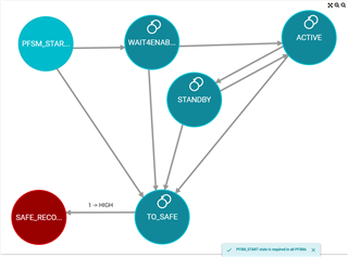
The state machine of the JSON template looks like following

Does this impact the functionality of the PMIC ?

Generic_TPS6594.json

  • Hi Dierk,

    I understand your confusion on this issue. There does not seem to be much information regarding the justification for the warning you have shown.

    To look into this, I changed the name of the STANDBY state in Generic_TPS6594.json to PFSM_START, as that is the state with no transition from another state. Is that what was intended?

    This resulted in the command TRIG_MASK to change from 0xFFFFFFF from the file without PFSM_START to 0xFFFFFFC from the file with PFSM_START. This change allows the device to respond to trigger priorities 0 and 1. When TRIG_MASK is 0xFFFFFFF, the device cannot transition from the first state it enters. The device will be stuck in the STANDBY state and not respond to the SU_ACTIVE or IMMEDIATE_SHUTDOWN triggers when they occur. 

    How was the template created? The GUI (version 3.0) has warnings in place that would not allow me to delete the PFSM_START state from the blank TPS6594x starter template shown below.

    Regards,
    Megan

  • Hi Megan,

    the JSON template was provided by Michael G. My customer is a newcomer to the GUI and wants to understand what these states are used for and if he needs to address the warnings for simple bring up of the rails. 

    Can you please explain the basics so my customer understands how to move forward with this JSON example.

    Kind regards

    Dierk Bronner | Staff FAE Automotive

  • Hi Dierk,

    I worked with Michael to figure out the template that was provided was created using version 2.0 of the GUI. Version 3.0 of the GUI added more feedback mechanisms to identify potential NVM issues, among other updates, which checks for the PFSM_START, TO_SAFE, and SAFE_RECOVERY states. These updates can be found in the GUI Revisions table of the Scalable PMIC's GUI User’s Guide (Rev. B). Be sure to use version 3.0 of the GUI. You can see what version you are using by clicking Help and then About in the GUI.

    I have attached a new template file that is compatible with the latest version of the GUI. This file uses the same static configuration as the file in the original post, but the state machine diagram contains the PFSM_START, ACTIVE, STANDBY, TO_SAFE, and SAFE_RECOVERY states. 

    Generic_TPS6594_GUIv3.json

    As for how to use the GUI, the NVM Configuration Page chapter of the Scalable PMIC's GUI User’s Guide (Rev. B) is a great place to start! Above the warning shown in the initial question, there is a short description of each of the states in the warning, which I have copied below and added some more detail from the datasheet. 

    "The user defined mission state PFSM_START is required to bridge between the hardware states and the missions states." TPS6594-Q1 has hardware states that are built into the device and cannot be changed. These include the NO SUPPLY, BACKUP (RTC backup battery), LP_STANDBY, INIT, BOOT BIST, RUNTIME BIST, and SAFE RECOVERY states. Each of these states are explained in the Fixed Device Power FSM section of TPS6594-Q1 Power Management IC (PMIC) for Processors with 5 Bucks and 4 LDOs datasheet (Rev. B). The mission states are what is being configured by the state machine. More states can be added, the triggers can change, and the power up and power down sequences can be determined for the mission states. The PFSM_START state acts as the entry point to the state machine mission states. 

    "The TO_SAFE state is required as the transition between mission states and the hardware state SAFE_RECOVERY." When an error occurs in the mission states, the device can respond by sending the device into the SAFE RECOVERY hardware state. All of the outputs are shut down, either all at once for an severe error, or in a predetermined order for a moderate error. The interrupts triggering these errors are explained in the Interrupts section of TPS6594-Q1 Power Management IC (PMIC) for Processors with 5 Bucks and 4 LDOs datasheet (Rev. B). The TO_SAFE state acts as the exit point of the mission states into the SAFE_RECOVERY state.

    For the TPS6594-Q1 to function properly, all three of these states listed in the warning need to be present in the state diagram. Additionally, the template includes the ACTIVE and STANDBY states. The ACTIVE state is the state where all of the rails are active. This state is where the device is powering the processor and there are no errors. The STANDBY state occurs when the output rails are not active but there are no errors. The device is able to be woken from this state to other states without triggering a restart. More states can be added for a more complex design.

    For more information on how to use the GUI to implement these states and the transitions between them, Scalable PMIC's GUI User’s Guide (Rev. B) can help. Detailed descriptions of hardware states, triggers, and interrupts can be found in the TPS6594-Q1 Power Management IC (PMIC) for Processors with 5 Bucks and 4 LDOs datasheet (Rev. B).

    Regards,
    Megan