Hi All,
I have aquestion about TL7660.
1) Can the TL7660 pass an output current (Iout) of 100mA?
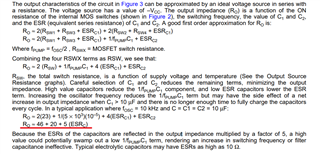
2) Does RSW fluctuate depending on the specification conditions?
Please tell me Min and Max of RSW.
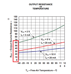
3) I have a question about the graph below.
Am I correct in understanding that when the IL current increases, the output voltage increases proportionally?
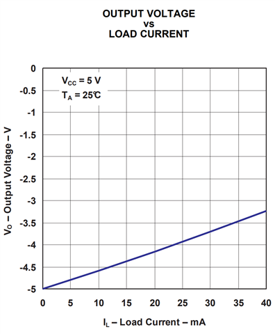
4) I have a question about the graph below.
Since IL=25mA when Icc=50mA, I think the efficiency η=50%, but the graph shows 90%.
Is the efficiency stated in the graph the input/output power efficiency? or efficiency by another calculation?
Best Regards,
Ishiwata