This thread has been locked.

If you have a related question, please click the "Ask a related question" button in the top right corner. The newly created question will be automatically linked to this question.

UCC28781-Q1: Feedback signal before vs after CM choke

Part Number: UCC28781-Q1
Other Parts Discussed in Thread: TL431

Hello TI,

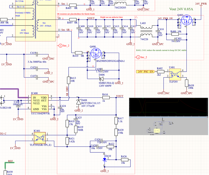
Would it be a good idea to place the voltage feedback signal  "VOUT" after the L403? Currently its at before the CM choke but it complicates the polygon pours + spreads the noisy path. Would be much better to use the clean "24V_PWR_SW" instead and change the GND at Tl431 to GND_SPC instead,

What do you think?

  • Hi,

    If after L403, the control object transfer function will become at least two orders higher which will require more complicated compensation network.

    In practice, you would need to decide which complication you would want to deal with.

    Most of applications would still connect feedback before L403 so to simplify the compensation network since the layout is much simpler compared to the additional network and the compensation turn-up.

    But it would be your choice you would like to try to see if you feel you are ok and should be good at tune up the compensation (loop gain, magnitude, phase, cross over f, etc), when you compare the feedback design to the layout design.

  • Thank you Hong,

    I did not realise it would be so complicated. In laymans terms, how would the output voltage change if i had it connected after L403? Would it start to become unstable?

  • Hi,

    When it is connect after L403 while you do not tune up your loop compensation, the output voltage can be unstable, or without adequate phase margin.