Hi team:
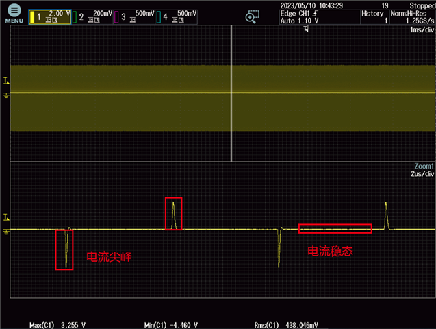
Q1:We have test the current from OUTA of UCC27524A1-Q1. As shown in the following figure,the voltage of the 1ohm resistance was measured of which the value is equal to the output current.The peak value is 0.438A,could you please help to confirm the risk? Thanks!
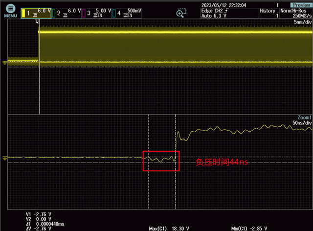
Q2:We have test the voltage of pin OUTA and pin OUTB of UCC27524A1-Q1.As shown in the following figure,the peak value is -2.85V when the low side FETs are about to switch.And it lasts 44ns.
Could you please help to confirm the risk? We need to know about when the body diode will be on and conducts the reverse current, how can we judge? Thanks!
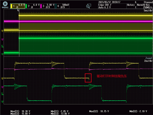
CH1: OUTA; CH2: OUTB; CH3: VDD CH1: OUTA; CH2: OUTB; CH3: VDD
Q3:We have test the voltage of pin OUTA and pin OUTB of UCC27524A1-Q1.As shown in the following figure,the peak value is 20.25V when the high side FETs are about to switch.Could you please help to confirm the risk? We also need to know about when the body diode will be on and conducts the reverse current, how can we judge? Thanks!
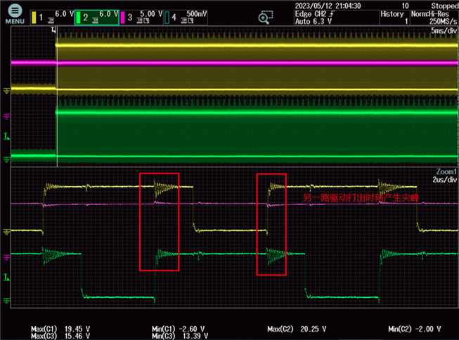
CH1: OUTA; CH2: OUTB; CH3: VDD