- Ask a related questionWhat is a related question?A related question is a question created from another question. When the related question is created, it will be automatically linked to the original question.
This thread has been locked.
If you have a related question, please click the "Ask a related question" button in the top right corner. The newly created question will be automatically linked to this question.
We are testing a TPS40211 evaluation board and have the current set at .55A by changing the resistor to .47 ohm. This works from 25C to 100C, constant current. However, from 25C to -30C it doesn't keep the current constant as well. Wondering if there are other tweaks to this circuit. We are driving an inductive coil for a load, 24VDC input to the board.
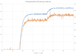
Also, we want to make the current soft start, ramp from zero current to .55A in 2 seconds. We tried changing the SS capacitor to .47uf and 4.7uf, the most we could get was 47ms and 470ms for a ramp. Do you only change the SS capacitor, or do we need to change something else to 'program this'?
Hi Tim,
Thanks for using the e2e forum.
For current limiting and managing the overcurrent threshold, the voltage at the ISNS pin is crucial.
According to the datasheet, the overcurrent threshold lies within 120mV and 180mV (150mV typical). This means, under different temperature condition, the threshold value might vary from the typical 150mV voltage. This has a direct impact on the current limit.
It would be interesting to measure the ISNS pin voltage during an overcurrent test and check at which voltage the FET is forced to turn off.
Regarding the softstart, the SS capacitor is the only way to 'program' the softstart time. However, if no capacitor with fitting value is available, the softstart time can be fine-tuned with a resistor in series to the cap, like seen in the TPS40210EVM schematic: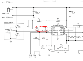
Best regards,
Niklas
Hi Tim,
As the softstart is commonly build within the timeframe of a few milliseconds, 2 seconds of slowly ramping up the output current might not be possible to realize with the softstart.
Even if the device is still in softstart state, the output current can already ramp up to the maximum value.
To limit the output current, I would suggest a different approach would be necessary.
I can check if we have any reference design for a similar application. However, due to high workload, it might take until earlier next week to get back to you with new information.
Best regards,
Niklas
Hi Tim,
Sorry for the long delay.
I have some additional insights from the team.
In general, you can either regulate for a controlled current, or a controlled voltage. With TPS40211, it should be possible to create a constant current ramp during start-up.
There are two things I would need feedback from your side:
- As the issue seems to appear only at low temperature, it might be related to the LEDs. Could you check the datasheet of the LEDs if there is any behavior change at low temperatue?
- To look deeper into the issue, would it be possible to send a waveform measurement of the start-up? The signals to look at would be
Vout, SS pin and FB pin
Thank you very much.
Best regards,
Niklas
I will look into the: Vout, SS pin and FB pin
By the way,
Niklas,
We are not using the eval board with LED’s as it was designed.
We are connecting to a coil (inductor), for a electromechanical clutch.
Hoping to gain constant current on the coil from -30C to 100C.
We are also looking for a solution to soft start another electromechanical clutch with a coil activation.
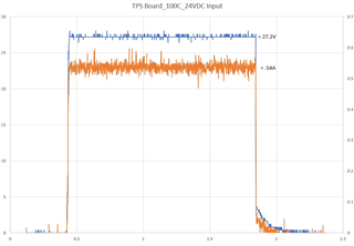
The attached is a 24V coil, activating the electromechanical brake at .5A, 24VDC applied to the TPS board input.
The plot is the output current and voltage from the board.
Tim
Hi Tim,
Thanks for the additional info and for preparing some waveform measurements.
For the 24V coil with electromechanical brake, are you referring to a specific design and plots?
I did not see any attachment, so maybe I overlooked something.
Thanks for clarifying.
Best regards,
Niklas
Hi Tim,
It would be ideal if you could directly attach the excel sheet here in the thread.
As we are several engineer from a team supervising the forum, files and messages get lost quickly if not all team members are involved in the mails.
If you cannot share design files on this open forum, please let me know and we will find an alternative solution.
Thanks and best regards,
Niklas
As far as I can tell, there is no way to attach an excel file. Only links can be attached.
Hi Tim,
Thanks for reaching out to us via e2e.
It is a bank holiday today. Please expect a response by Friday or Monday.
Best regards,
Feng Ji
Hello Tim,
Sorry for the late response. You can upload a file by using the Insert dropdown and use the second option "Image/Video/File".
Normally you should get the same current independent on temperature. If you share measurements, please explain which signals are seen.
Best regards,
Brigitte
Hello Tim,
We are currently looking into this and will be back with a response until mid of next week.
Kind regards,
Moritz
Hello Tim,
First of all, in a boost converter, there is a direct path from VIN to VOUT through the inductor and the diode. So the output voltage will follow the input voltage with some drop due to the diode directly when you apply the input voltage. Even if the device is disabled, you are getting VIN-Vdiode on VOUT. So independent of what capacitor you are using you will see first a jump to VIN and then when the voltage on SS exceeds the voltage on FB, the converter will start switching and ramp the output voltage to the set value.
You are right, the current should stay constant or almost constant independent of temperature. But if you get some shift in the measurement signal, e.g. due to humidity or due to GND shift, you might observe a current change. Could you please observe FB to IC GND while you measure the current and plot this as well? It is important that you measure with reference to IC GND, as this is the only GND signal the device is seeing.
Best regards,
Brigitte
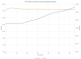
Brigitte, we are not so much thinking about the soft start anymore. However, if we can get the evaluation board to output a constant current no matter the temperature (also increasing the voltage with switching power supply), this would be useful as a product. We need to feed input 24VDC and get a constant .55A (about 18V at -30C and 32V at 100C). Right now, I don't think our TPS40211 board is working, see attached.
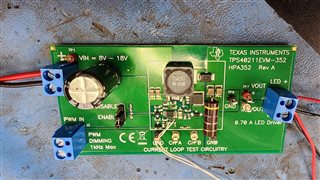
Hello Tim,
Which resistor are you using as sense resistor?
Your measurements show a feedback voltage that is changing from 150mV to 250mV. It should be a straight line at 260mV. So I wonder if the problem is the current demanded by your load. You mentioned that you have a inductive load. Is it possible to remove the inductive load to check if the EVM is then operating as expected?
Maybe the compensation needs to be optimized for your inductive load.
Best regards,
Brigitte
Brigitte,
We are using a .47 ohm sense resistor. The evaluation board says input should be 8V to 18V. We are supplying 24V. The output is 23V. I am not sure if this is okay. The coil load does have a reverse voltage spike when turned off. The current at 20C to the coil is .65A. What compensation are you talking about? Do you know how to do that? Otherwise is there another device that might work better with our coil load? LM25085 or..
At this point, my evaluation board may be bad. I have already replaced the MOSFET thinking I may have damaged it. There was no change in performance. But ordering another eval board like this one seems like it may not work without figuring out how to compensate for the different load. That's why I am asking about other parts and eval boards that may do similar things, not made specifically for an LED driver, which is not what we have.
Tim
Hello Tim,
It might be possible that a motor drive device fits better to your needs. Normally these devices are designed to drive inductive loads. But I think the converter is operating as expected, as you get a constant current.
As the converter seem to operate properly at room temperature and you get a fixed current, I wonder if the sense resistor you are using is changing the value over temperature. This would explain a change of the average current.
Best regards,
Brigitte