This thread has been locked.

If you have a related question, please click the "Ask a related question" button in the top right corner. The newly created question will be automatically linked to this question.

TPS55165-Q1: SMPS IC Burns at around 33V

Part Number: TPS55165-Q1

Hi,

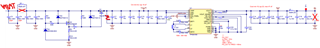
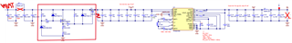
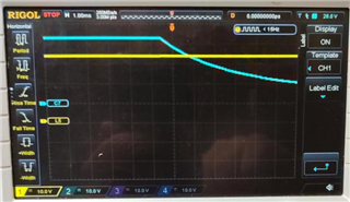
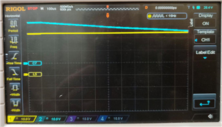
I am using TPS55165 in my circuit. I designed an overvoltage protection circuit to protect IC when an overvoltage occurs. SMPS IGN controlled by MCU. The overvoltage protection circuit works when the voltage rises over to 33V and cuts at 33V, but the TPS55165 IC is burned during the 33V or higher on-off operation. For normal operation, the TPS55165 IC works very well. The circuit schematic is attached.

  • Hi Egemen,

    What overvoltage protection circuit do you mean? At the input side or at the output side?

    Can you also explain the principle of the circuit here?

    Can you show the layout and the waveforms if captured when the IC is burned?

    Regards,

    Bryce

  • A circuit inside the red box is an overvoltage protection circuit at the circuit's input side. BZX384-B33 zener diode is used for the cut the voltage around 33V.

    The other 12V zeners are used to protect the gate of the FETs. Around 33V, Q2 (U1) operates, and Q1(U2) turns off, which cuts the voltage.

    Green is the input voltage from 0 to 80V

    Blue is the output voltage of the overvoltage protection circuit which is the input voltage for SMPS.

    I made the layout according to the TPS55165 datasheet recommended layout.

    There is no problem at the normal operating range such as 12V. But when the 33V or higher input voltage occurs, IC is damaged despite the overvoltage protection circuit works.

    I could not capture any waveforms when IC is damaged.

  • Hi Egemen,

    What is the input voltage range of VBAT?

    What about steady state operation at 35V over protection threshold? Can you test the input voltage at TPS55165-Q1 side pin4-5 if the protection circuit works?

    Also, can you remove TPS55165-Q1 and separately use scopes to test the over voltage protection circuit to see if drain voltage of Q1 is under 33V?

    Regards,

    Bryce

  • Hi Bryce,

    1) VBAT range is 8-32V but the overvoltage protection circuit is designed for automotive load dump

    2) Circuit cuts the input voltage at 33V, so I may not test this one.

    3) I shall try to scope in that way

  • Hi Egemen,

    Thanks for feedback.

    Is the 24V battery you are used in this project?

    Regards,

    Bryce

  • Hi Bryce

    It shall suit 12V and 24V batteries.

  • Hi Bryce,

    Measurements are attached.

    The TPS55165-Q1 is removed and the 470R load is connected to measure the drain voltage and the supply voltage (channels are labeled on the scope). At the exact 33V supply value, the circuit toggles due to no hysteresis at Q1's output.

  • Hi Egemen,

    Thanks for your waveforms.

    It looks the over voltage protection circuit works well. But TPS55165-Q1 should not damage at 33Vin. You can also try to trigger Vo or Vin or iL to capture the waveforms at the moment of damage.

    Could you recall the test condition when TPS551651-Q1 got damaged? Like Vin voltage, stable or on-off? Load current? So I can also do experiment with EVM.

    Regards,

    Bryce