This thread has been locked.

If you have a related question, please click the "Ask a related question" button in the top right corner. The newly created question will be automatically linked to this question.

BQ24172: BQ24172- POWER SELECT PROBLEM NO BATTERY CONECTED

Part Number: BQ24172

HI 

I  HAVE A CIRCUIT WITH BQ24172 AS CHARGER & ACFET& RBFET P.N CDS17309Q3.

I have designed this board mainly based on BQ24172EVM-706-15V board .

I HAVE NOTICED THAT 30% OF THE MANUFACTURED CARDS HAVE A PROBLEM OF POWER THAT DOES NO ENTER TO THE CIRCUIT

THROGH THE ACFET & RBFET. 

WHEN THERE IS NO BATTERY CONNECTED TO THE BOARD AND THE POWER SOURCE IS THE ADAPTOR POWER.

AT THE BQ24172EVM-706-15V board THERE ARE CAPCITORS   4.7nF & 47nF CONECTED TO ACFET.

I HAVE FEW Q.

-CAN I REMOVE THEM PERMANENTLY BECOUSE  AFTER REMOVING 4,7nf CAPACITOR  THE PROBLEM DISAPEARD.

- WHAT IS THE LOGIC BEHIND THE PROBLEM  & THE SOLUTION ?

-SHOULD I REMOVE THE OTHER CAPACITOR (47nF) HOW TO CALCULATE CAPACITOR NEW VALUES IF NEEDED ?

-ACCORDING TO THE DATA SHEET WHAT IS THE AMOUNT OF THE SURGE CURRENT WITHOUT THE CAPACITORS? 

THANK YOU

  • Hi Asher,

    The 47 nF and 4.02kohm RC is provides an RC smoothing of the ACDRV output to prevent over-voltage of the FET's gate and provide soft start.  The 4.7nF provides even more soft start.  If the gate capacitance of your FETs is close to either of those capacitances, you can remove the 4.7nF and possibly the 47nF.  The goal is turn on before the ACUV deglitch turn below:

     On your failing boards, I suspect you will measure that the OVPSET pin is not rising above the ACUV value before the 30ms time.

    Regards,

    Jeff

  • HI JEFF !

    THANK YOU FOR YOUR QUICK ANSWER.

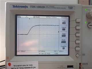
    I  TESTED THE  RISING TIME OF OVPSET TIME  AT THE FAILING CARDS AND THE RESULT WAS 15mSEC 

     THIS IS LESS THE 30mSEC .(SEE PICTURE)

    I   DONT FIND THE RESONE WHY PART OF THE CARDS DONT START UP WITHOUT BATTERY CONECTED.

    THE INPUT CAPACITANCE OF RBFET & ACFET ACCORDING TO THE DATA SHEET OF P.N CDS17309Q3

    IS 1150pF.

    WHILE THE CHARGER IS TRYING TO START UP THE POWER AT ACDRV IS TRING TO RISE AND ITS  FAILING

    I  ATTACHED THE PICTURE.

    I AM ALSO ATACHING THE  ECHARGER SCHEM.pdfLECTRICAL SCHEM OF THE CHARGER.

    ANY   ANOTHER IDEA WHER TO TEST?

    ASHER SELA

  • HI Asher,

    Can you take a failing IC and install on an EVM?  We need to see it is an IC problem or board problem.

    Regards,

    Jeff

  • hi jeff

    sorry for the delay

    i will try to put the ic at the evm

     "If the gate capacitance of your FETs is close to either of those capacitances, you can remove the 4.7nF and possibly the 47nF."

    any risk exist when removing those capacitors?

    asher

  • Hi Asher,

    As I said, if the capacitance is the same magnitude as the external caps, I see little risk.  I have not test without those caps.

    Regards,

    Jeff