This thread has been locked.

If you have a related question, please click the "Ask a related question" button in the top right corner. The newly created question will be automatically linked to this question.

BQ25504: MPPT is not working

Part Number: BQ25504
Other Parts Discussed in Thread: LM66200

Hi Team,

This inquiry is a follow up to the other E2E post below.

https://e2e.ti.com/support/power-management-group/power-management/f/power-management-forum/1236773/bq25504-energy-harvesting

I have some more questions about the JMCU-25504 (BQ25504) module. 

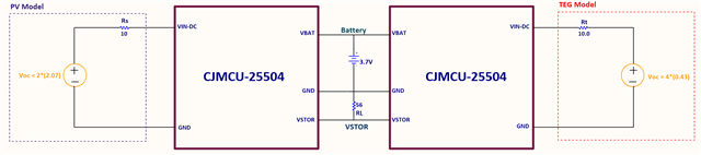
I changed the value of the resistors of the module according to the datasheet for the battery voltage of 3.7V.

ROK1 3.3M
ROK2 6.2M
ROK3 560k
ROV1 4.3M
ROV2 5.6M
RUV1 3.9M
RUV2 6.2M

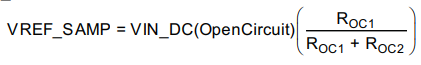
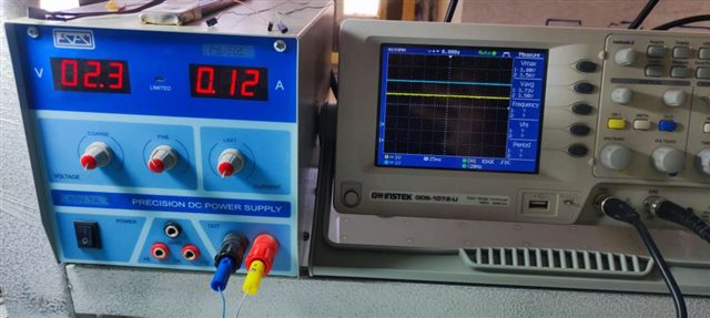
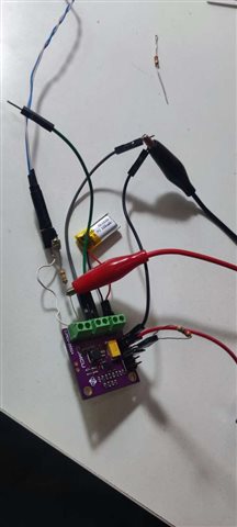
And in this step, I used a 3.7 V 100 mAh lithium battery with a 330 Ohm load and an input voltage of 2.3 V. But my circuit does not MPPT properly. I didn't change the MPPT resistors, but I don't know which pin I should put the jumpers on to make it MPPT. The voltage VOC-SAMP is very small (55 mV).

How should I use these 3 jumpers?

In the figure, the yellow graph is the VSTOR and the blue graph is the VBAT in the 330 Ohm load.

Is my circuit working properly?

And can Texas company suggest a thermoelectric generator (TEG) module that fits the input of the BQ25504 IC, while the dimensions of the TEG are very small?

Regards,

Danilo

  • Hi Danilo,

    The MPPT point is determined by the voltage at VREF_SAMP using the voltage divider from VIN_DC. It is given by the following resistor.

    Unfortunately I can't see the graph you meant to provide, was there an image or link you meant to add? For your input power source, do you have an I-V Curve and know the voltage of the MPPT point?

    And can Texas company suggest a thermoelectric generator (TEG) module that fits the input of the BQ25504 IC, while the dimensions of the TEG are very small?

    I will look into this and let you know if I've find one that is recommendable.

    Best Regards,

    Juan Ospina

  • Hi Juan,

    Thank you for your response.

    Please see attached picture of the waveform as well as the hardware setup of our customer.

    Regards,

    Danilo

  • Hi Danilo,

    What exactly is the waveform showing? Can you label the DC values with a cursor? What are the values of ROC1 and ROC2? How do you know the MPPT is not working?

    Regards,

    Mike Emanuel

  • Hi Mike,

    Please see the feedback of our customer below.

    Thank you for your response.
    I solved the mppt problem by giving an external voltage to the VREF pin, and the input current should not exceed 120 or 130mA!!.  If the current goes above this value, the circuit will no longer follow mppt.
    I did not change the value of the Roc resistors.
    I think the most is set to 78%.
    Now I need another input source for a hybrid with solar. I think thermoelectric would be suitable, but I haven't found a suitable TEG module at the moment, can you introduce me to an example that is suitable for the BQ25504 IC?
    The open circuit voltage of my solar is 2.07V and Pmppt =30.7mW, I want to connect several solar in series and parallel with each other.
    The average current consumption of my system is 60-80mA and the battery voltage is 3.7V.
    I want to do power for a wearable device like glasses that health monitoring.
    That means the output power I need should be approximately 300mW.
    Can I provide it?

    Regards,

    Danilo

  • Hi Danilo,

    I think thermoelectric would be suitable, but I haven't found a suitable TEG module at the moment, can you introduce me to an example that is suitable for the BQ25504 IC?

    We don't typically deal with too many TEGs so we don't really have any recommendations. They aren't as common because their output voltages are very low, around 100 mVs which is below the device's 600mV cold start threshold. Furthermore, some TEGs can output negative voltages so some rectification might be required. Ultimately I would look for a TEG with an output voltage higher than the cold start threshold. 

    Additionally, since you will be using two inputs, it may be necessary to change the VREF voltage divider if the MPPT point is different for the inputs. One way to do this may be by having a resistor in series with a FET to the reference point, thus allowing two selectable MPPT points.

    That means the output power I need should be approximately 300mW.
    Can I provide it?

    I think this will be dependent on the current consumption of your application. What is the expected duty cycle for which your device will be consuming the 80 mA of current and how much current and for how long will you be able to pull current from your solar sources?

    Best Regards,

    Juan Ospina

  • Hi Juan,

    Please see our customer's response below.

    Thank you for your response and support.
    I have two ideas for hybridization
    First, I use LTC4413 or LM66200 IC to hybrid the input sources and give them to the Vin cjmcu-25504 module.
    And the second solution is to use two cjmcu-25504 modules for each of the input sources instead of using the above ICs and giving their output to the battery (VBAT, VSTOR), I think that in this case, my circuit can simultaneously harvest the energy of both solar and TEG sources.
    If you have a better idea, please guide me.
    Regarding the thermoelectric module, 1MC06-126-03TEG seems to be suitable, if I connect several samples of them together in seris, it can reach the cold start voltage.
    The average consumption per hour is 60 to 80 mA. And every effort should be made to increase it to one week.
    Solar energy can be harvested during the day. (eg 12 hours)
    The solar model I chose is KXOB25-05X3F. And again, I will make 10 examples of them in series and parallel.

    Regards,

    Danilo

  • Hi Danilo,

    I'll have to investigate the possibility of using two sources to ensure there is no strange interactions, but you're right in that it would allow harvesting from both sources simultaneously.

    The panel you recommended provides about 30.7 mW of power at its MPPT (18.4 mA @ 1.67V), with a boost efficiency of about 88% around 3.7V VSTOR this is about 27mW. You mention consumption of 300mW per hour so you may be able to power your device if you have 23 solar cells (assuming 12 hours / 24 are providing full power and current consumption is 24 hours). It would be important to consider other potential sources or power loss.

    Best Regards,

    Juan Ospina

  • Hi Juan,

    Here is the comment of our customer.

    Unfortunately, due to my limited dimensions, I cannot use 23 panels. Maybe I can fit only 10 on the handle of the glasses.
    I just bought another module and plan to use it to hybridize both sources, one for solar and one for thermoelectric.
    But I don't know if it is correct or not.
    I have one more question
    What is the efficiency, loss, and power consumption of the IC?
    According to my calculations, the IC consumes high power?! For example, 20 or 30 mW

    Regar,

    Danilo

  • Hi Danilo,

    Efficiency is based on Input voltage and Current, thought it is typically 85-90%. You can view some typical efficiency curves in section 7.6 of the datasheet. If the TEG is expected to produce a known amount of power, you can reduce the number of cells needed.

    Best Regards,

    Juan Ospina

  • Hi Juan,

    Here is the response of our customer.

    But in my calculations, the efficiency is less than 80%. It is approximately between 60 and 80 percent.
    I have sent you my calculations and results for 4 thermoelectric modules connected in series in the picture below. I modeled it using a voltage source and a resistor in the lab, and according to the test results, my efficiency was 75%. Are my calculations below correct?
    Thank you very much for your guidance and support

    Regards,

    Danilo

  • Hi Danilo,

    It looks like some information from the customer might be missing.

    Best Regards,

    Juan Ospina

  • Hi Juan,

    I apologize that I was not able to post the computation from our customer. Please see the computation below.

    Regards,

    Danilo

  • Hi Danilo,

    I will attempt to recreate this scenario in my lab and update with my observed values. The calculations look reasonable.

    Best Regards,

    Juan Ospina

  • Hi Juan,

    Our customer would like to request an update to his inquiry.

    Thank you!

    Regards,

    Danilo

  • Hi Danilo,

    I'm working to put together similar calculations and putting together a board that represents similar resistor values to the ones you've provided. I'll be providing the measurements as soon as I can.

    Best Regards,

    Juan Ospina

  • Hi Danilo,

    I was able to gather the experiment with the following values:

    VIN: 0.889 V     IIN: 74.5 mA    PIN: 66.3 mW

    BAT: 3.668V     IBAT: 2.75 mA    PBAT: 10 mW

    VSTOR: 3.667V    RSTOR: 219.7 Ohms    PSTOR: 61.2 mW

    Efficiency: 61.2mW / 76.3 mW = 80%

    This is an more or less nominal value as it lies in the values between these two graphs in the range corresponding to 74.5 mA of input current, between the Red and Green Lines (VSTOR = 3.67), and between the the two graphs (Keithley source = 1.70).

    These factors indicate an efficiency expected of around mid-to-high 70's to mid 80s percentage wise. Is it possible that there is other resistances, current consumptions in the board design that may be affecting the efficiency measurements?

    Best Regards,

    Juan Ospina 

  • Hi Juan,

    Please see the response of our customer below.

    There is no other resistance on the board. I just used a 1-ohm resistor to measure the battery current.
    So it seems that my circuit calculations and performance are correct. it's true?

    Regards,

    Danilo

  • Hi Danilo,

    The calculations should be reasonable when taking into account potential variances resulting in a 5% difference from my measurements. The battery resistor should be taken into account.

    Best Regards,

    Juan Ospina

  • Hi Juan,

    Thank you for your comment. Our customer has follow up questions below.

    I just paralleled two Cjmcu25504 modules together. One module to harvest solar energy and another to harvest thermoelectric energy.
    I connected the VBAT pins of both modules (parallel), also did the same for VSTOR. And I got some interesting results.
    When the amount of load increases (56 ohms), both modules take energy and become mppt. But when the amount of load decreases (100 Ohm resistance), only the module that is on that load is mppted, and harvests the energy.

    Is this function correct? Do you have another idea for hybridization?

    Regards,

    Danilo

  • Hi Danilo,

    This is not a very common configuration (dual harvesters) so I will have to do some further testing and investigation to identify the exact  behavior and what is causing it. To confirm resistor values on both boards are sets to the same as described in the first post?:

    ROK1 3.3M
    ROK2 6.2M
    ROK3 560k
    ROV1 4.3M
    ROV2 5.6M
    RUV1 3.9M
    RUV2 6.2M

    But when the amount of load decreases (100 Ohm resistance), only the module that is on that load is mppted, and harvests the energy.

    From what I understand VBAT and VSTOR from both devices are connected in parallel. Can you explain by what is meant by: "only the module that is on that load". Since both are connected to the same VSTOR shouldn't both modules be on the load?

    Best Regards,

    Juan Ospina

  • Hi Juan,

    Here is the feedback of our customer.

    Thanks for response 
    Yes, the resistance values of the two boards have been changed in the same way for the voltage of 3.7 volts.
    ROK1 3.3M
    ROK2 6.2M
    ROK3 560k
    ROV1 4.3M
    ROV2 5.6M
    RUV1 3.9M
    RUV2 6.2M
    TI: Can you explain by what is meant by: "only the module that is on that load":
    I meant that the load resistor was connected on the VSTOR and GND pin of the cjmcu25504 which is PV, and then I connected it on the thermo energy harvesting board.

    The schematic of my circuit is as follows, which I tested in the laboratory.

    Regards,

    Danilo

  • Hi Danilo,

    Thank you, I will attempt to recreate this scenario.

    When the amount of load increases (56 ohms), both modules take energy and become mppt. But when the amount of load decreases (100 Ohm resistance), only the module that is on that load is mppted, and harvests the energy.

    Which of these modules do you observe being MPPTed? It sounds like if both modules are connected to the load, but it is a lighter load (100 Ohms) only one of the modules will harvest energy. Is this a correct understanding?

    Best Regards,

    Juan Ospina

  • Hi Juan,

    Please see this email from our customer.

    In the file below, I have included the tests I have done in the laboratory for better understanding. I hope you can help me. Are my results acceptable?
    Why is it that even though the VSTORs of the two boards are connected in parallel, when the load is light (100 ohms), the module closer to the load MPPTs?
    I still don't understand why.

    I am looking for a rule and algorithm for this structure

    Hybrid-CJMCU25504-Lab-Tohidinejad.pdf

    Regards,

    Danilo

  • Hi Danilo,

    Thank you for the documents that clarifies things greatly.

    I've recreated a similar setup in my bench. In my scenario, I am able to consistently draw power from both sources to both charge the battery and power a 200 Ohm load. The only reason I can think that results in one module entering MPPT when the load is placed near but the other not, and the opposite happening when the load is placed on the other board is that the trace resistance from the setup (wires, breadboard, PCB) is increasing the resistance seen by the further module at VSTOR. Can you try wider gauge wires and possibly direct connection from one module to the other at VSTOR to see if that affects behavior?

    For the circumstance where VBAT < VBATOV (Battery should be drawing current) and both sources are connected, are both sources providing current and in MPPT? I would expect both modules to be sourcing current and in MPPT if the battery is below VBATOV regardless of a load presence.

    Best Regards,

    Juan Ospina

  • Hi Juan,

    Thank you for your help.
    I changed the voltage sources of the two boards today. 
    I modified the right board for thermoelectric voltage, and also the left board for solar voltage (document).
    My circuit no loaded.
    And both boards were MPPT.
    That means the battery was charging, positive battery current of 78.3mA.
    In this situation, I put a 100 Ohm load on each of the thermoelectric and solar boards as before, and contrary to the previous results, both boards became MPPT.
    As a result, I immediately repeated the voltage sources and tests similar to the submitted document. And in this situation, it didn't matter where the 100ohm load was.
    Are these results and my build generally correct?
    I can use this method for hybridization.
    Or do you suggest another method?
    Thank you in advance for your help.

    Regards,

    Danilo

  • Hi Danilo,

    It looks like you were able to achieve a scenario of both input sources achieving MPPT both while charging and while loaded. This seems to indicate the system is working as expected!

    In terms of hybridization this method should work as long as the battery configuration for both modules match. The previously explored method of multiple input sources may work for your application however it does provide the limitation that only one source will work at a time. Ultimately, I recommend testing the set up with your expected battery solution and input sources to confirm behavior with the actual PV / TEG sources you expect to use.

    Best Regards,

    Juan Ospina

  • Hi Juan,

    Please see our customer's response.

    Thanks for the reply

    I also think so, that this is the correct scenario.

    The solar arrays are located outside the building and under the sunlight. And the thermoelectric voltage was modeled in the laboratory similar to the previous state. I got the following results.
    In this case, both boards are MPPT. Are these results acceptable? And the efficiency of 94% correct?

    Reards,

    Danilo

  • Hi Danilo,

    Yes, these calculations look correct. Both boards in MPPT indicate both sources are being drawn from to power the load which indicates a correct scenario.

    Best Regards,

    Juan Ospina

  • Hi Juan,

    Thank you for your help.

    Regarding MPPT, my circuits are MPPT with external voltage reference. But without that, MPPT reference cannot be done.
    At this point I connected my solar panel to the board with no external reference voltage (no potentiometer), my Panel was in front of the sun and its open circuit voltage was 3.55V. But when I connected it to the CJMCU-25504 module, its terminal voltage dropped a lot (to millivolts). And my circuit is not MPPT. What is the reason for this?
    What should I do to track the MPPT if I want to get my results with an actual solar panel?
    Another question is, voltage dividers are poison for wearable systems because they have a lot of losses. However, is the BQ25504 IC suitable for these wearable applications?
    And the next question is, what is the strong argument for presenting my proposed structure for hybridizing thermoelectric and solar modules? Because this IC may be less efficient for thermoelectric sources than solar energy. I am looking for an excellent reason to introduce this structure.

    Regards,

    Danilo

  • Hi Danilo,

    I connected my solar panel to the board with no external reference voltage

    At this point can you clarify the schematics for this situation? Are the pins VOC_SAMP and REF_SAMP pins floating or pulled to ground?

    t this point I connected my solar panel to the board with no external reference voltage (no potentiometer), my Panel was in front of the sun and its open circuit voltage was 3.55V. But when I connected it to the CJMCU-25504 module, its terminal voltage dropped a lot (to millivolts). And my circuit is not MPPT. What is the reason for this?

    Without the reference voltage the device does not know the MPPT voltage of the source and will attempt to pull as much current as it can from the solar panels, likely causing them to drop dramatically in voltage past the maximum power point. The device will need a voltage reference, typically through voltage dividers, in order to achieve optimal power harvesting.

    voltage dividers are poison for wearable systems because they have a lot of losses

    This is why we typically recommend voltage dividers on the order of MegaOhms. With a voltage divider total resistance on the order of 10 MOhms, and a Vbias of about 1.21, the consumption of the dividers should be on the order of 0.12 uA which would reduce losses.

    However, is the BQ25504 IC suitable for these wearable applications?

    I believe this depends on your application and tolerance for quiescent current consumption as well as your battery capacity and expected device run-time. Leakage current for the IC represents its current consumption from various pins and in various modes:

    And the next question is, what is the strong argument for presenting my proposed structure for hybridizing thermoelectric and solar modules?

    I'd say the largest advantage provided by hybridizing is that you can source power that doesn't solely rely on sunlight. That being said this would require an investigation on how much more power is likely to be harvested from the thermoelectric generators in practice in order to measure the impact of this additional benefit.

    Best Regards,

    Juan Ospina

  • Hi Juan,

    Please see our customer's response.

    I didn't know the settings of the jumpers. So today I realized that I need to connect one of the jumpers to OCS and R_DIV.

    Because I thought that the module is MPPT by default and the jumpers are to disable MPPT.Sweat smile 

    I think that connecting jumpers is not clear for users.

    Thank you very much for your team's support and response.

    Regards,

    Danilo

  • Hi Danilo,

    I'm glad you were able to resolve it and I'm happy to help.

    Best Regards,

    Juan Ospina