This thread has been locked.

If you have a related question, please click the "Ask a related question" button in the top right corner. The newly created question will be automatically linked to this question.

LMG3522EVM-042: Issue connecting evaluation boards in series configuration

Part Number: LMG3522EVM-042
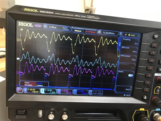
We designed and tested ANPC 3 phase first with three of these evaluation boards and as the results were not expected we tested on 1 phase, with low voltage and low switching frequencies. The result was good until a certain voltage and after that, the output phase voltage was messed up. These voltages were different in different switching frequencies. For example, it was 12V for a 50kHz switching frequency. To find out the issue, we used evaluation boards in different configurations like H-bridge (two devices in parallel) and voltage source inverter (VSI) (three of them in parallel), and the results were good. Hence, connecting them in parallel does not have any problem.
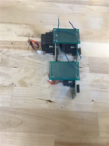
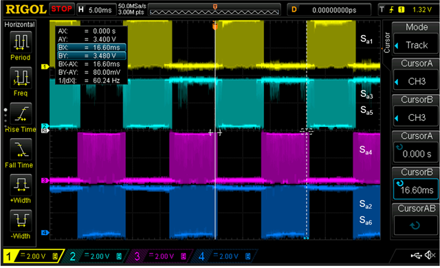
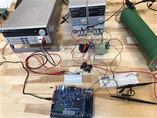
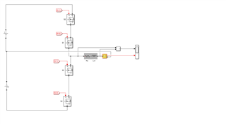
However, whenever we want to connect two of at least in any configuration, some switches went fault. For example, by connecting two of them in series where the top device with two switches (S1, S2) was ON during the positive period and the down device with two switches (S3, S4) was ON during the negative half cycle, and 50kHz, the result was expected until 20V and after that, the fault appeared in S3. I am sending a picture of connecting two of them in a series, where we used an AC power source to power two RECOM Power, RAC02E-05SK/277 to isolate the gate driver inputs. FPGA outputs were going for the PWMs and two DC power supplies for each evaluation board.
We were wondering what we should do with the series connection configurations. Is there any wrong with our connection? I appreciate it if you can help us and share your opinion and suggestion about it.  
Thanks,
  • Hello Adel,

    Thanks for the post, please give me 24 hours to review your question specifically with ANPC applications.

    Regards,

    Zach Soviero

  • Hello,

    I have a couple questions to help my understanding of your setup. First I'd like to narrow down which fault event is triggered in the devices and then work backwards to find the issue. Can you share you sequence of input signals for the GaN FETs? Perhaps there is a shoot through event which would cause and overcurrent fault in the device.

    Also, any other information you can share would be helpful, a measurement waveform of the event if possible. 

    Regards,

    Zach Soviero

  • Hello Zach,

    Thanks for helping. We first divided the 3-phase ANPC into one phase. Three evaluation boards are used there like a picture attached. Two of them are in series naming switches S1, S2 (first EVM) and S3, S4 (Second EVM) and then connecting the third EVM and switches as S5 and S6. By connecting them the first place fault happened was S3. The sequence of signals is as in the second picture with the labels. As this problem happened we checked other inverter configurations. Then we concluded that the series connection is the problem. Then we checked just two devices as discussed before. We measure the load voltage and the current in that case as in the picture. The PWM signal of S2 is dark blue, light blue is the current through S2, purple is the V_ds of S2, and yellow is the load voltage. As you can see when the S2 PWM is zero there is still a current flowing there.

  • Hi Adel,

    Our applications engineer Zach was out of office yesterday and not able to respond. He will be back today and have a response this afternoon.

    Best Regards,

    Kyle Wolf

  • Hello,

    I apologize for the long delay, I have some thoughts and additional questions that may help narrow the issue.

    First, I'd like to see if you can verify the switching order of FETs to insure there is sufficient dead time and no shoot through occurring. You stated that the current measurements are being shown in the scope picture but I'd like to confirm how those measurements are being acquired, the scope is showing a voltage division for all 4 channels so I am slightly confused here. If you could tell or show me the value for current measurement that would be helpful.

    In addition, there will always be some resonant current in this circuit because of the very large LC component, the resistance you have pictured is quite large and could be contributing to the ringing significantly. I suggest that you possibly reduce this resistance temporarily to see if the smaller inductance helps with ringing.

    Regards,

    Zach