


Dear Sir/Madam,
I have built new prototype boards with the LM25116. This acts to convert the main input power (8 - 32 V) to a regulated 5V supply for my board. Max current drawn is a theoretical 1.2 Amps but is usually closer to 0.4 Amps.
I have an issue where about half the boards I have built have issues where the LM25116 output becomes unstable. On some of these problem boards it can operate correctly for over an hour before the output becomes unstable. What is unusual is that the schematic design is coppied from an earlier board design which had no issues with the LM25116.
In order to trouble shoot, I have replaced the LM25116 with a fresh unit, disconnected the 5V supply to the rest of the circuitry on my board and just connected the 5V to ground via a 10 kOhm resistor.
What I have seen is that in the fail state:
- The 5V output from the LM25116 circuit is actually 0V.
- The HO and LO outputs to the switching mosfets are both set low.
- I also see that the UVLO pin is pulled down to 560 mV.
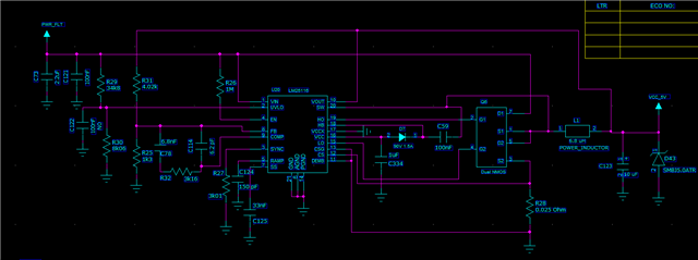
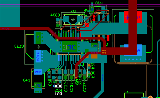
Below is my schematic and layout files.
Note that C122 on the UVLO line is not inserted. D43 is a TVS diode, I have also removed this in my latest experiments.
If you have any feedback on how to debug this issue I would really appreciate it.
