- Ask a related questionWhat is a related question?A related question is a question created from another question. When the related question is created, it will be automatically linked to the original question.
This thread has been locked.
If you have a related question, please click the "Ask a related question" button in the top right corner. The newly created question will be automatically linked to this question.
Hello
I'm facing difficulties to check the stability margin with Bode 100 on a flyback built around UCC2801.
The flyback is in inverting step up mode with the following param :
Vin=19V...29V
Vout=-50V, Iout=30mA
DCM mode chosen with Duty cycle < 0.46 over the full operating range
The SIMPLIS schematics is the following:
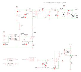
The UCC2801 model is derivated from UC3842 and is not 100% correct. I modify some internal parameter to have a plant transfer function matching from my prototype to the simulation.
In the prototype, the op amp inverting the feedback is an OPA192 (final choice will be OPA237).
Lp=40µH, NS/NP=5
Fsw=115kHz
I performed the compensation to get a fc=2kHz and a phase margin of 70°.
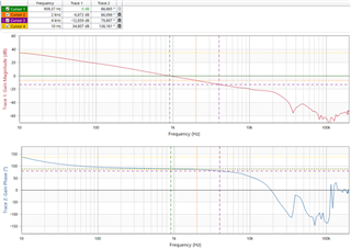
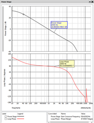
Plant transfer function comparison
When I compare the measurement and simulation of the plant transfer function I get close results:
Compensator transfer function comparison
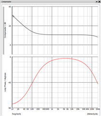
When I compare the compensator transfer function I get strange results with the BODE 100:
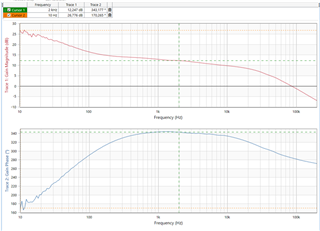
The phase is not in line with theory and simulation below 200Hz :
Loop gain comparison
And the loop gain is also different from simulation and measurements :
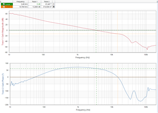
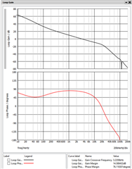
It's the first time I perform stability margin checking on a flyback in an inverting step up configuration.
I don't understand the phase on the loop gain below 200Hz. Is it a measurement issue ?
I think so because the transient is correct :
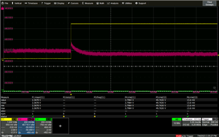
(yellow trace is the image of the 30mA load step).
Can you give me advice to check carefully the stability with this configuration ?
If needed, I can share my prototype schematics and my simulation file but it should be done via MP or email as it's confidential.
Thanks for your support
Hi Lionel,
Thank you for the query on UCC2801. This has been assigned to an expert who will be looking into this.
Regards,
Hi,
Please send your prototype circuit, your simplis model and your test and simulation results to hong_huang@ti.com
Hi,
As no additional response, I will close this thread. If you need support, you can re-open this thread or create a new thread.
Hi,
Sorry, I should say we are in email communication so this thread is ok to close. Besides, i sent the email to you with my suggestions but I have not received any response from you, so I am assuming you have solved the issue. If not please let me know through email.