This thread has been locked.

If you have a related question, please click the "Ask a related question" button in the top right corner. The newly created question will be automatically linked to this question.

TPS2116EVM: TPS2116 : Current consumption when pullup resistor is used on ST Pin

Part Number: TPS2116EVM
Other Parts Discussed in Thread: TPS2116

Good evening, 

I am currently using TPS2116EVM, I have connected two amperemeters on VIN2 and VIN1 inputs (both are operating at 3.3Volts) to check the current consumption. I have connected a Load Resistor of 10kOhm instead of using the 10R Load Resistor on VOUT as I need to measure the leakage current when my device is in sleep mode ( approx. 330uA).

I need to use ST Pin to create an Interruption on the MCU when the Power path change.

when ST Pin is pulled up to Vout  (config, with JP5 Jumper), I have observed a current consumption 660uA on VIN2 (when selected ) and +540 uA on VIN1 (when selected).

If I leave ST Pin floating or if I connect ST Pin to PR1 , I have a current consumption of approx. 330 uA on both VIN1 and VIN2. I confirm the quiescent current of TPS2116 .

It seems having ST pulled-up to Vout is considered as a load , and I would like to optimize the power consumption of my board.

I see several solutions:

- Using a higher Impedance pull-up 1 to 10 MOhm to decrease the current consumption

- connecting ST Pin to PR1, then I need to provide a higher voltage on VIN1 (on the EVAL board) due to Heresis effect ( I am using your excel document provided on the forum) , 

- pulling down ST PIn with 10K ohm resistor, 

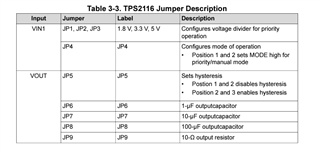
I have noticed a small mistake on the table 3.3 , page 3 of the Eval board user guide ( ref SLVUBZ0A – NOVEMBER 2020 – REVISED DECEMBER 2020)

maybe you meant

Position 2 and 3=> disable hysteresis

Position 1-2 => enable Hysteresis

thanks for your support, 

damon

  • Hi Damon, 

    When ST is HiZ when IN1 is selected, the ST pin should only leak a maximum of 0.03uA. 

    Is this happening across multiple boards, and could you provide a scope shot of this leakage? 

    To your second point, yes you are correct: the JP5 description is incorrect. The positions should be flipped as you have noted. 

    Best Regards, 

    Elizabeth 

  • Dear Elizabeth, 

    sorry for the delay, I wanted to setup a new installation and retest everything.

    I am using a 6 1/2 digit 34411A agilent amperemeter to measure the leakage current on VIN1,

    the TI eval board I am using is the TPS2116EVM, REV. A and I have only one purchased recently.

    I am using JP5 Jumper to test different config on ST Pin

    Test condition 1 : VOUT is connected to VIN1 (4VDC), No load  , leakage current is measured at VIN1 Input

    if ST is left floating:  leakage current is 270uA 

    If ST is connected to Vout with 10K RES: leakage current is 270 uA 

    If ST is connected to PR1 through 10K RES: leakage current is 270 uA 

    Test condition 2 : VOUT is connected to VIN2, No load , leakage current is measured at VIN2 Input

    if ST is left floating: leakage current is 0.8uA to 1.3uA

    If ST is connected to Vout with 10K pullup: leakage current is 400 uA

    If ST is connected to PR1 through 10K RES: leakage current is 0.8uA to 1.3uA

    Test condition 3 : VOUT is connected to VIN1 (4VDC), 100K Load , leakage current is measured at VIN1 Input

    if ST is left floating: current consumption 310uA

    If ST is connected to Vout with 10K RES: current consumption 310uA

    If ST is connected to PR1 through 10K RES: current consumption 310uA

    Test condition 4 : VOUT is connected to VIN2,100K Load , leakage current is measured at VIN2 Input

    if ST is left floating: current consumption 41 uA

    If ST is connected to Vout with 10K pullup: leakage current is 430 uA

    If ST is connected to PR1 through 10K RES: current consumption 41 uA

    Test condition 5 : VOUT is connected to VIN1 (4VDC), 100K Load ,  R5 = 1MOhm +10KOhm ( I have added a 1MOhm on JP5 Jumper), leakage current is measured at VIN1 Input

    if ST is left floating: current consumption 310uA

    If ST is connected to Vout with 10K RES: current consumption 310uA

    If ST is connected to PR1 through 10K RES: current consumption 310uA

    Test condition 6 : VOUT is connected to VIN2,100K Load , R5 = 1MOhm +10KOhm ( I have added a 1MOhm on JP5 Jumper) leakage current is measured at VIN2 Input

    if ST is left floating: current consumption 41 uA

    If ST is connected to Vout with R5 = 1MOhm +10KOhm pullup: leakage current is 45 uA

    If ST is connected to PR1 through 10K RES: current consumption 41 uA

    My assumptions: Leakage current on VIN1 is too high, maybe this power input was damaged. connecting ST to Vout through a pull-up will bring a leakage current ( same than a load resistor).

    ON my future board design, I need to use USB power and backup battery ( Lithium 3.6V). I will connect USB power to VIN 1 and backup battery on VIN2 as the leakage current is lower lower. I will use a pull-up resistor with high impedance ( 1 to 4.7Mohm). 

  • Hi Damon, 

    Yes as you have seen in your experiment, when IN2 is selected, ST is pulled to ground. At this point, there is a path for current to flow from VIN2 to Vout to ground when VIN2 is selected. 

    This produces a current path equal from Vout to ground equal to VIN2/R5. 

    We do not test for high impedance pull ups from ST to Vout, so please confirm your system is working as you intend. There might be some voltage drop on ST from Vout or delay due to parasitic capacitance. 

    Best Regards, 

    Elizabeth