This thread has been locked.

If you have a related question, please click the "Ask a related question" button in the top right corner. The newly created question will be automatically linked to this question.

TPS65262: Questions about LDOs: in parallel and undervoltage

Part Number: TPS65262

Hey!

Two quick questions about the LDOs in the TPS65262. We are looking to use two TPS65262, and the LDOs do not provide quite enough power. Looking for 250mA, where the LDO max is 200mA. Our idea is to connect the inputs of two LDOs and connect the outputs of two LDOs.

My questions are:

1) Could we connect the inputs of two LDOs and the outputs of two LDOs? (Either on same TPS65262 chip or different chips, doesn't matter to us. Whichever you recommend)

2) What is the behavior of the LDO when Vout is set to 5V and the LDO input voltage is lower than output voltage? Will it passthrough? Passthrough is ideal, I want to make sure there is no under voltage lockout or anything of that sort specific to the LDOs

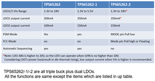
(Another note, I looked at the -1 and -2 versions which have the larger LDO output current limits but one version doesn't have automatic sequencing, and the other version has too narrow a LDO vin (5.5Vmax))

  • Hi Cameron,

    Thanks for reaching out! I will check and get back to you soon. Thanks!

    BRs

    Lucia

  • Hi Cameron,

    • It's not recommended to connect the inputs of two LDOs and the outputs of two LDOs to get parallel LDO, because the equaled current flowing in 2 LDOs can't be assured. Thus they cannot be used in parallel. If the 2 LDOs are used in parallel, when add loading, they will work in below way: one of LDOs will not provide any loading, (Marked as 1st LDO) the other LDO will provide whole loading until reach it's OC limit (Marked as 2nd LDO),  then Vout will drop a little, and the 1st LDO will start to provide loading to keep Vout, when both LDO reach OC limit, output will shut down.
    • Please kindly find the difference between TPS65262, 2-1, 2-2 shown below:

    Kindly let me know if there is anything unclear.

    BRs

    Lucia

  • equaled current flowing in 2 LDOs can't be assured

    Why is this? I’m guessing the voltage drop across the pass element would vary chip to chip from manufacturing. So more current would pass through one LDO vs the other LDO. 

    if there’s enough headroom, I believe this should be ok. Are you able to test on two eval boards in parallel? 

    (say our load is 150mA maximum, use LDO2 of first chip in parallel with LDO2 of second chip which would allow 200mA in parallel maximum. This feels ok to me.)

    2) What is the behavior of the LDO when Vout is set to 5V and the LDO input voltage is lower than output voltage? Will it passthrough? Passthrough is ideal, I want to make sure there is no under voltage lockout or anything of that sort specific to the LDOs

    could you please comment about this too? 

    thanks,

    cameron 

  • Hi Cameron,

    I can share you the bench test results based on EVM board soon.Thanks!

    BRs

    Lucia

  • Hey Lucia, About the LDOs in parallel, I did some more digging.

    Unrelated app note about LDOs in parallel uses ballast resistors on the LDO outputs to make sure the current through them stays consistent. Personally I've never used these ballast resistors before, looks like a solution I will suggest to the customers.

    (https://www.ti.com/lit/ug/tiducs7/tiducs7.pdf)

    Appreciate you working in the lab, thank you!

  • Hi Cameron,

    Thanks for sharing this app note.

    2) What is the behavior of the LDO when Vout is set to 5V and the LDO input voltage is lower than output voltage? Will it passthrough? Passthrough is ideal, I want to make sure there is no under voltage lockout or anything of that sort specific to the LDOs. --It's passthrough. May I know the reason that you need passthrourgh behavior.

    BTW, I am still doing the measurement on EVM about parallel LDOs. Will feedback to you soon.

    Thanks!

    BRs

    Lucia 

  • Hi Cameron,

    For the EVM bench test results of two LDOs parallel, please kindly see feedback shown below:

    (1) As you can see from above EVM schematic, both LOUT1 and LOUT2 are set as 5Vout. Connect LVIN1 and LVIN2, connect output of LDO1 and output of LDO2.

    (2) When add loading, LDO1 will not provide any loading, LDO2 will provide whole loading until reach it's OC limit (LDO2 typical OC is 180mA). It means that when loading < 180mA, the load current is all supplied from LDO2, Vout is around 5.01V. When load current > 180mA, LDO2 overcurrent is triggered and Vout will drop a little (Vout is around 4.97V) and LDO1 will start to provide loading to keep Vout. When both LDO reach OC limit (LDO1 typical OC is 330mA), output will shut down. This is the behavior from EVM that the equaled current flowing in two LDOs can't be assured. That's the reason why it's not recommended.

    (3) Could customer use TPS65262-1/-2? The LDO output current is 300mA for them.

    Thanks! Kindly let us know for anything unclear.

    BRs

    Lucia

  • Hey Lucia,

    Unfortunately, we are stuck with the blank version because the -1 version has too narrow an LDO input voltage. The -2 version has no automatic sequencing. 

    The idea we are looking at is using 2x TPS65262 in parallel. So LDO1 in parallel with another LDO1 with ballast resistors on the output. I don't see a reason why this wouldn't work as long as the ballast resistors are large enough:


    May I know the reason that you need passthrourgh behavior.

    This is a product in an airplane cockpit. There are requirements for them to supply power for a certain amount of time if aircraft power is lost. To achieve this, they have a big capacitor bank. The LDO passing through is ideal behavior, because their system will continue to operate as 5.0V drains to 4.5V as the capacitor bank is emptied and passes through the LDO

  • Hi Cameron,

    • Thanks for your feedback about the reason they could not choose -1 and -2.
    • Would you please also share me the customer of this requirement? What is the system input voltage range? How many Buck converters rails and LDO rails they need? What is the load current requirement for each rail? It would be really appreciated if you could share me a block diagram. You can also send me an email (lucia-gao@ti.com) if you prefer to talk by email. 
    • For the method you mentioned above about how to parallel, I am not sure whether TPS65262 can also work in this way, but I can check on EVM boards.

    Thanks!

    BRs

    Lucia