This thread has been locked.

If you have a related question, please click the "Ask a related question" button in the top right corner. The newly created question will be automatically linked to this question.

TPS40345EVM-353: Short-circuit simulation

Part Number: TPS40345EVM-353

Hi TI Staff,

I simulated the eval board in both LTSpice and PSpice for TI, while output voltage matches with the description of the eval board, but the short circuit current limit was different.  Here are screen shots for both simulation tool:

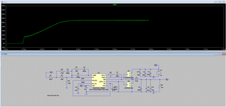
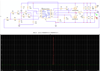
LTspice indicated short circuit current limit kicks in close to 120A, where PSpice for TI shows a 60A spike.  The datasheet suggested 20A as the short circuit limit, which I have verified on the eval board.  The question is that what I can do to improve the simulation and how do I adjust the short circuit limit?  The datasheet shows calculation for R11, which affects the short-circuit limit, however I cannot find that part on the schematic nor on the PCB board.

Thanks,

Dave

  •  

    The datasheet shows calculation for R11, which affects the short-circuit limit, however I cannot find that part on the schematic nor on the PCB board.

    It's R1 in your schematic above. from the LDRIV/LIM pin to GND.  A current is forced on the pin as part of start-up to create a voltage, that voltage is then used to as a threshold for the PGND to SW drop during the low-side FET ON time.

    The question is that what I can do to improve the simulation and how do I adjust the short circuit limit?

    First check to see if the two simulations are using the same MOSFET Rdson / Drop during the low-side FET on time

    Second, the models are likely using nominal threshold values where the datasheet equations are set-up for worst-case values

  • Hi Peter, 

    Thank you for your feedback.  I still have a couple questions regarding the OCP function.  Originally, I had the same thought as R1 is the R_OCSET resistor, but the value that eval board used (4.02k) is different than the calculated value (7.1k in section 8.2.210).  Reading section 7.3.5 of the datasheet agrees with what you said, but I just have no idea where the 4.02k came from AND somehow it sets the CO level correctly.

    First check to see if the two simulations are using the same MOSFET Rdson / Drop during the low-side FET on time

    Second, the models are likely using nominal threshold values where the datasheet equations are set-up for worst-case values

    I dropped in the TI models for those FETs.  But I will try to verify the Rdson and drop for those FETs.  Good pint on the worst-case values, I will double check on that as well.

    Thank you,

    Dave

  • Hello Dave, 

    David is out of office, so i am covering here 

    Thank you for your feedback.  I still have a couple questions regarding the OCP function.  Originally, I had the same thought as R1 is the R_OCSET resistor, but the value that eval board used (4.02k) is different than the calculated value (7.1k in section 8.2.210).  Reading section 7.3.5 of the datasheet agrees with what you said, but I just have no idea where the 4.02k came from AND somehow it sets the CO level correctly.

    Just follow the equations in the datasheet and use the RDSON that is used in your application. The datasheet equation example used 4.6mohms RDSON that is not the same as with the EVM that uses the CSD1632Q5 with lower RDSON. 

    Thanks 

    Tahar

  • Thank you Tahar, this makes sense.