This thread has been locked.

If you have a related question, please click the "Ask a related question" button in the top right corner. The newly created question will be automatically linked to this question.

UCC2894: Active clamp pulse

Part Number: UCC2894
Other Parts Discussed in Thread: PMP7391

Hello Team,

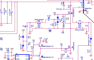
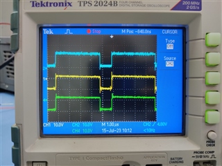
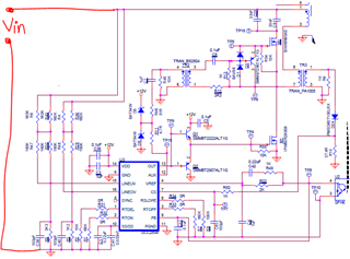
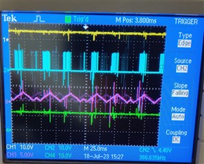
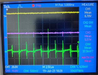
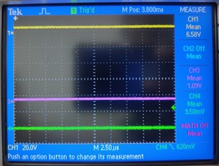
I/m working with UCC2894 PWM controller and I have referred "PMP7391" reference design of TI for active clamping circuit. The blue waveform is @TP15, yellow waveform is @ primary winding of TR2 and green is @ secondary winding of TR2. The yellow waveform is shifting towards negative side, why is that so? The value of TR2 is 350uH.


  • Hi,

    How did you connect your oscilloscope probe to TR2?

    Was your oscilloscope channel setup DC or AC?

  • The probe was connected across pin 4 and 6 of TR2.

    The channel was set to DC coupling.

    Another problem seen is that the voltage @ Vss pin is getting low as the Vin voltage crosses approximately 30V and thus the GATE pulses turn OFF. The voltages @ Vref, Vdd, LINEUV, LINEOV, Vfb are as per the required conditions. So what may be the reasons of voltage dip @SS/SD pin. The circuit is @ no load condition.

      •                  Fig-1                                                                           Fig-2
    • In the image above Yellow is Vref, Blue is Vout, pink is Vss and green is Vdd, the out pulses show such behavior after Vin reaches 26V approximately and after increasing Vin further the pulses turnoff completely i.e. Vss voltage drops as shown in Fig-2. 
  • Hi,

    C7 charged up when AUX is high so when AUX is low TR2 is with voltage C7 so it is revered or shifted.

    Can you capture CS waveform to see how much voltage on CS pin when SS started discharge?

  • Thankyou for the explanation of shifted pulse.

    Yellow - Vref, Pink - Vss, Green - Vcs.

    The voltage @Vcs also goes to zero as Vss goes to zero. The reason for Vcs to get low may be as the gate pulses turn OFF due to drop in Vss voltage. There is no load connected to the output of the supply.

    What may be the possible reasons for Vss to go low?

  • Hi,

    The green is Vcs, 500mV/div, its voltage reached above can go over 6V based on your waveform. It is possible to trigger an internal hiccup OCP which purposely to prevent the damage when CS pin sensed a high voltage.

    I suggest to find out the reasons why there are very high voltage CS spikes and resolve this to see if the unexpected soft start discharge can be resolved.