This thread has been locked.

If you have a related question, please click the "Ask a related question" button in the top right corner. The newly created question will be automatically linked to this question.

BQ25121A: SYS @1.4V

Part Number: BQ25121A
Other Parts Discussed in Thread: BQ25121

Hi there

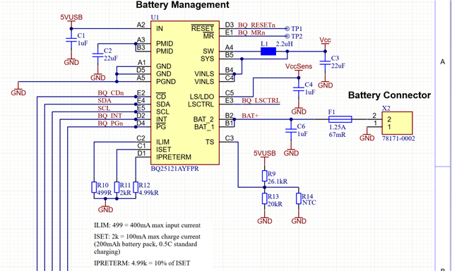
My current design contains a BQ25121A for battery management. After being attached to a power supply (USB) for approx. 12hrs, the BQ25121A has only 1.4V at VSYS. I could not find any state in the datasheet, where the chip should output this voltage. If the design is not attached to the power supply or not in sleep mode (sleep current <1uA), the issue is not reproducible.

Thanks for some hints and BR

Urs

  • Hi Urs,

    To clarify the USB power supply is connected at VIN and the device is left alone for 12 hours. The initial VSYS voltage then drops to 1.4V? I have a few questions for further clarification of the situation:

    - What is the voltage and input current for VIN? Can you measure how much current the device is pulling from VIN while SYS is at 1.4V?

    - What is Battery, PMID, and MR voltage when SYS is 1.4V?

    - What is the /CD pin state when SYS is 1.4V (floating, pulled up to VSYS, other?).

    - Is I2C communication possible at this point and if so, can you provide a register dump of the device?

    - Lastly, is there any load present on the device during the 12hr test?

    I hope that we can get a better idea of the cause with some of these answers.

    Best Regards,

    Juan Ospina

  • Hi Juan

    Thanks for you quick reply!

    Yes, VSYS is configured to be 3.3V, which is the case for the "normal" working state, after X hours (at least 12hrs, sometimes 24-36), the voltage drops to 1.4V, but I do not have an exact scope measurement of this drop currently.

    Measured when VSYS was at 1.4V:
    - VIN: 5.05V, <1mA (my tool is not more accurate)
    - with the current design, I can not easily measure the current drawn by the device (between VINLS/VSYS and the device)
    - VBAT 4.51V, @VBAT <1mA, when USB is unplugged it goes down to 4.25V
    - PMID 5.05V
    - /MR 4.45V
    - /RESET 2.9V
    - /CD 0.6V I tried with 2 different configurations, when pulled to GND (for low power mode), the issue tends to occur earlier than when pulled high. But with VSYS at 1.4V, my MCU is anway in a not defined state (BGM220SC22HNA2 SiP module), the minimal operating voltage is 1.8V.
    - I can not read the registers of the BQ25121 at such a low voltage
    - the load is very minimal during this time, there is a 2 second period where the MCU wakes up, measures for a few milliseconds (approx. 1-2mA) after that the system goes into sleep mode again (<1uA)

    Following the schematics of the BQ25121 circuit. ILIM, ISET and IPRETERM are reconfigured by the MCU via I2C.

    Thanks for your help and Best regards,

    Urs

  • Hi Urs,

    Thank you for the additional context. 

    The sufficient VIN and PMID voltage as well as a high BAT voltage and small load makes it not immediately obvious what may be causing this behavior. It looks like the IC has sufficient sources to pull from in order to power the SYS regulator.

    Are you able to tap into the I2C lines externally? I would like to confirm that VSYS isn't being accidentally set to 1.4V by accident via the register. Also, If possible, can you provide a VPMID and VSW and VSYS waveforms? I'd like to confirm that the Buck regulator is still switching rather than just having been disabled.

    Regarding your schematic and measurements, it's unexpected that you are measuring 0.6V on /CD. Is this while it is set high or low? /CD can be left tri-stated or floating as it has an internal pull-down to ground. Is BQ_MRn connected to an MCU GPIO or a switch? MCU GPIO's sometimes use a pull-up resistor to MCU VCC which can sometimes back feed current into VCC from BAT (through the MR to BAT internal pull up resistor). This might be something to take into consideration.

    Best Regards,

    Juan Ospina

  • Hi Juan

    To read the registers during fail state, I need more time to prepare a setup. See the zip file for the waveforms. I have attached one of /CD as well, during normal operation, the behavior is as expected. In fail state, where I measured 0.6V it should be high though. BQ_MRn (and BQ_RESETn) are left unconnected.

    4278.waveforms.zip

    Thanks again and Best Regards

    Urs

  • Hi Juan

    Ignore the waveform of /CD, I have just recognised, that it caught the wrong pin during waveform measurement (and therefore the 0.6V are wrong as well)! At the moment I need to wait until a device is in the fail state again, sorry for that!

    BR

    Urs

  • Hi Urs,

    Thank you for your update. Based on the SW waveforms it seems to indicate that the buck is definitely still enabled, and at a low load since it is in PFM rather than PWM control for the buck based on SW_1. If that is the case it appears that the buck is intentionally regulating to 1.4V. You've mentioned that this behavior is not reproducible if not attached to power-supply or not in sleep-mode. Does this mean that the device will keep SYS = 1.8V if a power-supply is not attached or if /CD is held low (for sleep / HiZ mode)?

    By the way looking at your schematics a bit more closely, I noticed that your LSLDO pin is missing a capacitor for the output. You may want to consider it for output stability from this line. 

    Best Regards,

    Juan Ospina

  • Hi Juan

    At the moment I keep the 3.3V during power down as well, which is working fine (without USB attached). The previously posted schema was outdated actually, this is the correct one:

    Anyway, I believe, I have got a solution in the meantime. Sometimes the IC went into error state due to a TS fault, even with disabled TS function, what could be the reason for this? In my opinion it has to do with this somehow. I changed my MCU code a little bit. As soon as BQ is in fault state (register 0x00, B6/7 = 11) I toggle CD (was the case before already) but in addition I rewrite all registers, what I did before only at startup. I have devices running for >48h now without issues so far.

    Best regards

    Urs

  • Hi Urs,

    Sometimes the IC went into error state due to a TS fault, even with disabled TS function,

    I don't expect that the TS function may be the direct cause for the 1.4V SYS behavior as TS functionality should only have an effect on reducing charge current or regulation voltage. Just to confirm, you identified the TS fault based on REG0x02 BITS 5 and 6? I wouldn't expect a TS fault if TS remained disabled (REG 0x02 BIT7 = 0).

    I rewrite all registers, what I did before only at startup.

    I'm glad that this has resolved the behavior you were seeing. This solution leads me to believe it may have been related to register configurations. 

    At the moment I keep the 3.3V during power down as well

    Just to clarify this 3.3V refers to the LSLDO rail? If that is the case and you plan use the LSLDO rail in the future you may want to connect VINLS to PMID rather than SYS since you expect SYS to operate at 1.8V.

    Best Regards,

    Juan Ospina