This thread has been locked.

If you have a related question, please click the "Ask a related question" button in the top right corner. The newly created question will be automatically linked to this question.

TLV61046A: TLV61046A has no Voltage and current output

Part Number: TLV61046A
Other Parts Discussed in Thread: TLV61046,

Hi everyone:

As the title, I assembly circuit with datasheet example circuit

I replace R1 and R2 with 470k and 82k to output voltage about 5.38 voltage.

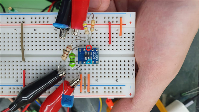
This picture is my actually circuit and component, I added 100 ohm load


I've tested the circuit for both short and open. 

I'm sure that connection of circuit is no problem.

But result is no current and voltage output.

This picture is test at Vo

This picture show no current output for my power supply(sourcing TLV61046)

Actually, I doubt this IC is fault, so I take 5 tlv61046 for test same circuit


Result is the same: No current and voltage output.

Does anyone help me?

Many thanks!

  • Hi DeWei,

    Pleas see attached picture.

    the red point should be EN pin, and the blue point should be FB, right?

    it looks that you directly connect the FB with the input. This will cause the device output 12V.

    but your EN is 0, so the device doesn't work.

    Please double check this.

    Best Regards

    Fergus

  • Hi Fergus:

    Thanks your reply.

    > the red point should be EN pin, and the blue point should be FB, right?

    No, EN pin is blue point, and FB pin is red point.

    My SMD transfer board labeled pins number is wrong.

    So please ignore numbers on the SMD transfer board

    Best Regards

    De Wei

  • Hi De Wei,

    I used to guess that if you have connected the FB resistor to the EN pin.

    As you said your pin number is wrong, please ensure the connect outside connection.

    it is recommended to check the input pins' voltage.

    the correct one should be :Vin 5V, EN 5V, GND 0V, SW 5V.

    Best Regards

    Fergus

  • Hi Fergus:

    Sorry I reply too late.
    I've measured and the pin voltages seem to be correct:

    Pin1, Vin: 5.1V (USB)

    Pin2, GND: 0V

    Pin3, En: 5.1V (USB)

    Pin6, SW: 5.1V

  • Hi DeWei,

    here are some workarounds for your reference.

    1. You can apply for a EVM of TLV61046A or I can send one to you.

    you can check the device on the EVM to see if your devices are OK.

    2. it is noticed that your mentioned PIN1 VIN PIN2 GND,

    but actually, PIN1 is SW and PIN2 is GND even you make the chip upside-down, the adjacent connection should be not changed.

    it always confuses me that you said the pin map is wrong, please confirm the pin connection.

    3. what about the FB and VOUT voltage?

    please test from the pin in case bad connection.

    Best Regards

    Fergus

  • Hi  Fergus:

    1) The FB point I measured earlier is 0.04V

    2) I'm interested about EVM board, how do I apply for it. Could you give me URL?

    3)  Here photo I enlarge with my microscope from above bread board circuit

    Are IC pins number I labeled correct?

  • Hi Dewei,

    The PIN number is correct.

    and the correct PIN number:1SW 2GND 3FB 4EN 5VOUT 6VIN

    Please refer to my first reply, it loos that your 3FB pin(blue) is connected to 5V and your 4EN pin(red) is connected to two resistors.

    For the EVM sample, you can apply it on https://tisamples.ti.com/.

    Best Regards

    Fergus