This thread has been locked.

If you have a related question, please click the "Ask a related question" button in the top right corner. The newly created question will be automatically linked to this question.

TPSM63606E: TPSM63606EXTRDLR

Part Number: TPSM63606E

Hello,

 I have few questions about P/N:  TPSM63606EXTRDLR. 

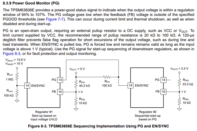
  1. In TPSM6360x Quickstart Tool – revA the Power Good indicator is connected to VCC pin with Rpg = 100Kohm.
    In TPSM63606EXTRDLR EVM electrical schematic the Power Good indicator is connected to Vout pin with R8 = 49.9Kohm.
    What is the correct way to connect the Power Good indicator ?

        2.  In TPSM63606EXTRDLR EVM electrical schematic – Are there any specific notes on the filter damping network ?

        3.  What is the purpose of R2 (10ohm) in the TPSM63606EXTRDLR EVM electrical schematic ?

 Thanks,

Shay.

  • Hi Shay,

    See my responses to each point below:

    1. PG can be connected to VCC or VOUT depending on what voltage you want to pull down when FB drops out of regulation. Connecting PG to either signal will have the same effect.

    2. The primary purpose for the filter damping network is to provide enough damping resistance either by a standalone resistor or internal resistance of bulk electrolytic cap. The details on this design can be viewed in the following app note section 1.5.

    3. R2 in the schematic is a bode injection resistor. Usually this resistor ranges from 10 ohms to 50 ohms and provides the nodes for ripple injection on a frequency analyzer for generating a frequency response plot.

    Regards,

    Henry