Other Parts Discussed in Thread: UCC24624
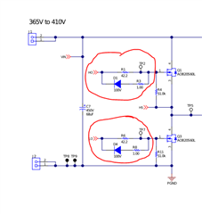
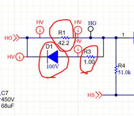
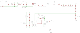
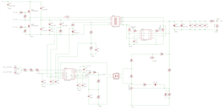
I have recently designed an AC-to-DC power supply (100-250VAC input, 18VDC 8A output) using the UCC28056B as a PFC boost converter and the UCC256404 and UCC24624 as a resonant LLC converter with synchronous rectifiers. See the schematic images below for details.
To design it, I used TI Power Designer and the IC datasheet information + Excel design tools (see the filled out versions posted below) as a baseline, as well as the provided SIMPLIS models and testbenches for tuning, simulation, and compensation loop design.
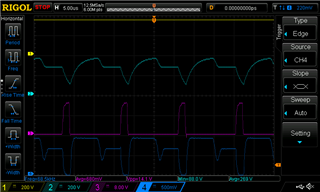
I have built a prototype of this design, starting with the UCC28056B PFC boost converter alone, which appeared to work correctly on its own (with an external VCC supply).
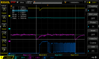
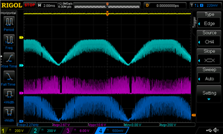
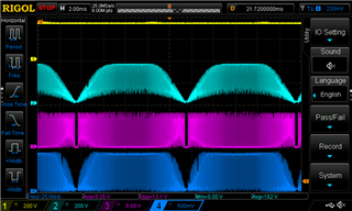
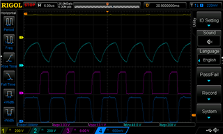
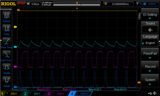
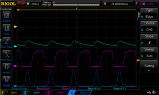
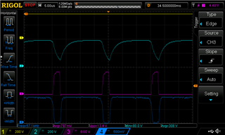
However, once I tested the complete prototype (with LLC converter, no output load applied), a few seconds after applying the input voltage (240VAC 50Hz), both LLC converter MOSFETs failed simultaneously, in a short-circuit mode (measured after the failure).
I measured the circuit before testing it, to ensure voltage divider values are correct and there were no short circuits or other previously identifiable problems.
I have no immediate clues as to what's wrong with my design to make such a failure happen and I don't know how I can test the circuit or figure out the problem without immediately destroying more components. Can you see anything wrong with my design? Do you have any hints for how I can fix my design to prevent such a failure from happening again?
Thank you very much in advance.
Kind regards,
Alexander Kharitonov
 7658.UCC28056X_Design Calculator.xls8080.UCC25640x Design Calculator Rev4.0.xlsx