This thread has been locked.

If you have a related question, please click the "Ask a related question" button in the top right corner. The newly created question will be automatically linked to this question.

TPS27SA08-Q1: Stange behaviour at turn on

Part Number: TPS27SA08-Q1

Hello,

we are using the TPS27SA08-Q1 smart high side switch (referred to as HSS in the following) as an power distribution switch in a racecar for formula student. More specifically, we have a power distribution pcb where the current from a 24V Li-Ion Battery is distributed on 4 HSS. We have several wiring harnesses which then are connected to the 4 HSS. Mostly there is one wiring harness connected to one HSS, but as we have more wiring harnesses than HSS, we need to connect two wiring harnesses to one HSS as well. All wiring harnesses and the battery are connected to the same GND star point.

We have experienced some strange behaviour depending on the configuration. 
First of all, each wiring harness works correctly, when it is connected to one HSS by oneself. But when we connect two wiring harnesses to the same HSS, there are problems.

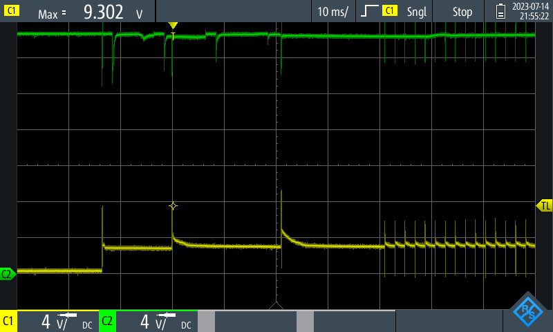
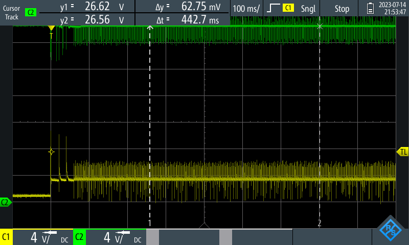
I have attached two screenshots from the oszilloscope where two wiring harnesses are connected to one HSS. In green you can see the battery voltage, in yellow the output voltage of the HSS.
When setting EN high, the HSS tries to switch on but goes into fault state 3 times followed by retry. I assume this fault is caused by the overtemperature protection as we have high inrush currents (which I could see in another measurement). But I can't explain what's happening after that. Apparently the HSS switches on and off with a much higher frequency. The output voltage remains at around 3-4V. This state is then permanent. The EN pin stays high all the time, LATCH pin is permantly pulled low.

Do you have an idea what is happening here?

Regards,
Andreas

  • Hi Andreas,

    Your output capacitance is large and the load is quite high. The device is constantly retrying into a capacitive load and hitting current limit and thermal shutdown. 

    I would recommend reducing your capacitive load to see successful turn on or using one switch per harness.

    For more information on driving capacitive loads, please refer to the following document: https://www.ti.com/lit/an/slvae30e/slvae30e.pdf 

    Thanks,

    Shreyas

  • Hi Shreyas,

    thanks for your fast answer. The capacitve load was my first assumption as well, but i don't think it is the (only) reason.

    I have tested the switch with a load consisting only of electrolytic capacitors with a capacitance of around 4mF (this is a higher capacitance than in our wiring harnesses). This worked fine, as you can see in the following picture. In green you can now see the output current of the switch, yellow still shows the output voltage of the switch.

    Similarly to my first post, the switch goes in current limit and thermal shutdown. But the output voltage rises continuously until it reaches the input voltage and the switch in fully turned on. This is the behaviour i expect according to the datasheet.

    Do you have any other guess what can cause the problem?

    Regards Andreas

  • Hi Andreas,

    During a capacitive inrush, this device clamps current. It hits thermal shutdown, recovers and retries. If your output load discharges the capacitance faster than the device can charge it up during the retry cycle, it is possible to reach a state of continual retry. 

    Thanks,

    Shreyas