


Non-isolated gate drivers are used in battery applications. This will go over multiple different applications, the benefits of using a non-isolated gate driver in the design, and which non-isolated gate driver to use.
Battery Monitor Devices
The BQ769x2 battery monitor device family has integrated high-side gate drivers for driving gates controlling the charging and discharging of the battery. When low-side switching is required, the battery monitor has digital charge and discharge signals that require external low-side gate drivers. In these cases, low-side FETs are used to control how exactly the battery and the charger source or discharge load are connected at the negative terminal. The purpose of the gate driver is to level shift the digital logic signal to the appropriate level to turn on and off the charge and discharge FETs. The driver is needed so that an increased number of FETs can be used with quick and efficient switching speed. The increased switching speed helps to put the battery into safe operation faster in the event of a fault.

Figure 1. Battery Monitor Circuit
TIDA-010216 - 16s Battery Pack Reference Design with Low-Side MOSFET Control for Large Capacity Applications
The TIDA-010216 uses the UCC27524 low-side gate driver in combination with the BQ76952 and is a good example of gate drivers assisting battery applications. The battery pack is designed to work with Li-ion and LiFePO4 batteries. It monitors different parameters that would cause cell degradation, thermal runaway, and explosion if not properly operated. The design prioritizes high-precision monitoring and protection while maintaining a low current consumption to allow for longer storage time and energy savings. TIDA-010216 uses five pairs of low-side MOSFETs with the UCC27524 driving five gates each with its output channels. The UCC27524 enables the BQ76952 to drive more MOSFETs allowing for support of larger battery capacity. There is an additional UCC27517 low-side gate driver for the pre-discharge MOSFET assisting with the discharge process.

Figure 2. TIDA-010216 Circuit
The UCC27524 offers a peak current of 5A for source and sink, 13ns propagation delay, and a small 1ns matching delay between its dual channels. The 5A drive strength allows for the control of multiple MOSFETs enabling a high discharge current. A newer version of the UCC27524 is available, the UCC27624. The UCC27624 has a higher voltage supply limit and a wider range transient voltage handling.
List of relevant parts for this application:
|
Device Name |
Drive Strength |
Propagation Delay |
Use |
|
5A |
17ns |
Dual channel |
|
|
10A |
17ns |
Single channel |
|
|
2.5A/5A |
17ns |
Single-channel with 8V UVLO |
Additional Information for this application:
Application Note – Using Low-Side FETs with the BQ769x2 Battery Monitor Family
DC/DC Converter in Battery Charger
This is a Phase-shifted Full-bridge (PSFB) converter, a type of DC/DC converter. Each pair of switches such as Q1 and Q2 is called a leg. A half-bridge driver is utilized to create efficient and fast switching. Each gate driver has a 50% duty cycle between the high-side and low-side pair in the leg. The legs are then kept out of phase of one another as demonstrated in the figure below.

Figure 3. PSFB Topology
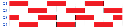
Figure 4. PSFB Timing Diagram
This type of switching is called zero voltage switching (ZVS) because there is zero voltage across the MOSFET at time of switching. This is done to minimize switching losses, especially with higher voltage inputs.
PMP10110 - Universal AC Input to 30Vmax@6A Lead-acid Battery Charger Reference Design with PFC
In the PMP10110, the AC input voltage must be converted to an intermediate DC voltage via a PFC converter stage, the intermediate DC voltage must be converted again via a DC/DC converter stage.

Figure 5. PMP10110 DC/DC Stage
This DC/DC converter has only one leg so instead of having ZVS there is soft switching, a small voltage difference across the MOSFET at time of switching. The UCC27714 supports HB voltages up to 640V. The UCC27714 also has a 4A drive strength and robust transient voltage handling.
PMP21529 - 4-Switch buck-boost bi-directional DC/DC converter reference design
The PMP21529 is a battery backup that uses a bidirectional DC/DC converter to charge a battery until DC bus power is cut off. The design then detects the power loss and changes the direction of the current to discharge the battery back to the DC bus. The design is also able to detect when best to use buck, boost, or buck-boost charging to most efficiently charge or discharge the battery.

Figure 6. PMP21529 Circuit
The UCC27211A is a half-bridge drive utilized for its 4A peak current and 20ns propagation delay. This allows for the design to operate and switch between its charging modes.
List of relevant parts for this application:
|
Device Name |
Absolute Maximum Bus Voltage |
Output Current |
Propagation Delay |
Use |
|
640V |
4A |
90ns |
High voltage |
|
|
120V |
4A |
20ns |
High frequency |
Additional Information for this application: