This thread has been locked.

If you have a related question, please click the "Ask a related question" button in the top right corner. The newly created question will be automatically linked to this question.

TPS56C230: double pulse problem

Part Number: TPS56C230
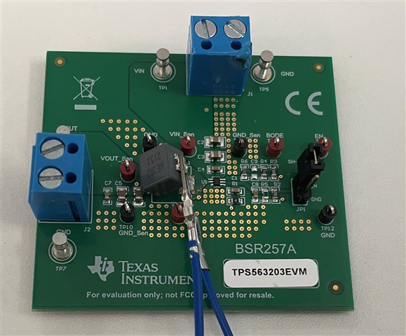
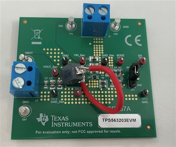
Other Parts Discussed in Thread: TPS563203
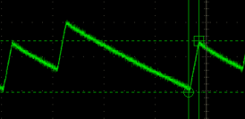
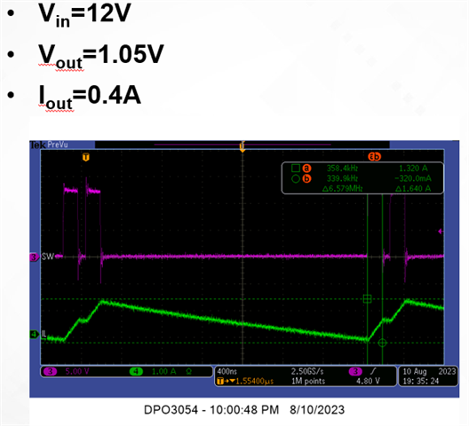
When I use this chip for remote feedback, a double pulse phenomenon will occur. As shown in the figure, the inductor current will be charged twice, but this will not happen for the near-end feedback. Can you tell me why? 
  • Hi Qingze,

    Is it possible to share additional details like schematic and how the remote feedback is being implemented on the TPS56C230 design used? This device does not have differential remote sensing capability.

    Thanks,

    Amod

  • The feedback is connected to a remote load, such as Vcore, in addition to PWM's Dynamic Voltage Scoling
  • I’ll review the schematic and layout and provide feedback by Monday. 

    Thank you,

    Amod 

  • Thank u,
    The same situation happened to me on the TPS563203 board today, and I hope it will be helpful to share with you. I wanted to observe the inductor current, so I lifted the inductor up and connected a Dupont wire. The probe is on the SW, but at a certain angle. I had the same double pulse problem, which disappeared after changing the wire.


  • Qingze,

    Thanks for sharing additional information on the TPS563203. I see that you opened another post on it and the respective expert will answer it.

    The schematic looks fine to me.

    • What is type of load used when testing without remote load - eload or resistive? Also, is the loading at the remote point fast changing or steady? Do you have any waveforms for the load current in addition to VIN, VSW?
    • Is it possible to label or show clearly how the routing from the output cap to the top resistor of the FB divider network?
    • On the remote sense, I assume VDDC and VDDC_VSEN are connected to each other. I assume VDDC_VSEN is the net connecting to the remote load, is that right?
    • Can you show the routing from the top resistor of FB divider network to the remote load VOUT and also from bottom resistor of FB network to the remote load ground? 
    • Also, how much output cap is present at the remote load? 
    • What is the input voltage and load current at which you are observing the double pulsing? Does it occur at all lower or higher IOUTs too? And, does this change with higher or lower VIN?

    It is hard to say exactly what may be causing the double pulsing but it can be related to stability (additional cap at remote load) and/or also noise introduced on the routing from remote load to the IC. 

    Thanks,

    Amod

  • I will supplement your above question based on what I know.

    • I am using electronic load, this power output is mainly for the core of the SOC, and it will change in the case of overclocking, so the PWM with DCA is added to participate in the adjustment. The waveform of the load current will be sent to you via Webex after I finish the test today.
    • I send you the picture via Webex to show detail.
    • VDDC_VSEN is the network connected to the remote load, VDDC is the voltage after the output capacitor, there should be a trace between the two voltages.
    • I will also use Webex.
    • I don't know the upper limit of the output, but it is about 1.1V now, I don't think it will exceed 2V.
    • The input voltage is 12V, the load current is 2A, 3A, I will change the load current according to what you said, change the input voltage and give you feedback through Webex.
      I think the layout affects FB's feedback, as you said, but I don't know how to measure this problem


  • Hi Qingze,

    It looks like the TPS56C230 VOUT plane is routed to the remote load VOUT (the green wide area?). Can you please confirm if that is the case? Ideally, they should just use sense lines on another layer to connect the VOUT from the TPS56C230 (from output cap) to the remote load. Also, the same applies to the top FB resistor routing. Also, you can have ground sense line from the bottom FB resistor to the remote load ground. You can try an experiment with the TPS56C230 EVM and connect the remote load (with similar capacitor configuration) with a long wires of about equal length for VOUT and GND connections and see if you still get the multiple pulsing issue. I recommend testing with a resistive load if possible instead of an active eload or use the eload in a CR or constant resistor mode. See if that helps.

    In addition to the above, can you please also tell me the amount of capacitance present at the remote load as well any other cap the TPS56C230 ends up driving. We need to ensure the capacitance is within the stability limits for the TPS56C230.

    Hope this helps.

    Thanks,

    Amod

    • For FB, C9, C10, C11, C7, and C8 are all output capacitors. The green area of ​​copper laying is not the remote feedback. The remote feedback is through R687, then through a via to R686, and then to Vsense (I will clearly mark the picture and send it to you via webex), Although I use a multimeter to test that the Vsense corner of R686 and the place where the copper is laid are conductive.
    • For Vout, I haven't found out how VCC is connected to VCCsense. I guess it has something to do with the green copper laying. I didn't find any connections and vias in the middle. You can also help me take a look.
    • I will test with resistors and EVM.
    • VSENSE should be directly connected to Vcore of SOC without capacitor.
      Can you give more suggestions for testing, I am still a little confused and don't know how to start


  • Qingze,

    I need to know the information I asked for without which we cannot determine if stability or noise is causing the issue. I understand there are caps C7 to C11 at the output of TPS56C230 but that is not what I am asking. In addition to those caps, at the remote load, there are additional caps, right? What is the cap configuration - how many caps and what is the total value?

    It looks like on the layout, there is not enough information from customer with you. I suggest checking with the customer for their PCB files so we can check all the layers of the layout. Without this, you may not be able to find information on how the remote sensing is being implemented and also if there are sense lines or just a VOUT plane being used to connect to the remote load.

    We can continue our conversation via email if you like. If so, please send an email with these answers. 

    Thanks,

    Amod