This thread has been locked.

If you have a related question, please click the "Ask a related question" button in the top right corner. The newly created question will be automatically linked to this question.

LM5122: 24 to 72V 16A dual phase Boost converter testing and final functions

Part Number: LM5122

Hi sirs

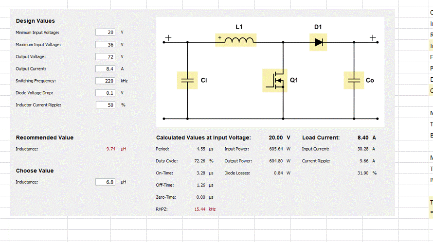
I was able to achieve 600W per phase with LM5122 with JUST 1X HS FET and 1X HS FET Slight smile 

Finally 16 A dual phase interleaved operation with $4 - 6.8uH inductor

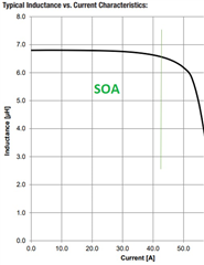
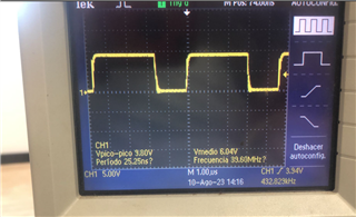
LM5122 internal gate Driver is not able to drive a single mosfet faster than 75ns

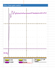
Gate driver is not strong and fast enought to switch the gate rise time at 18ns but external driver has done the magic
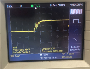


Questions

1 When converter is off, 24V IN appears at the output (OV at UVLO pin) -> i want to completelly have 0v when converter is OFF

2 How can i set a shunt value of +/- 1.8 miliohm for porotecting inductor at 0.075V/41A ?

3 Additional Suggested testings and measurements from your side 

if possible contact me at <nacho.diz@eesl.es> to kept this as confidential

  • Hi Ignacio,

    whow, this is really impressing - thanks for sharing.

    To your questions:

    When converter is off, 24V IN appears at the output (OV at UVLO pin) -> i want to completelly have 0v when converter is OFF

    Due to the body diode of the high side FET this can not be avoided.
    To get this either an additional Switch or additonal circuit needs to be added (may check here: Power switches | TI.com)
    or the power supply needs to be done with a 4 switch buck-boost topology.

    2 How can i set a shunt value of +/- 1.8 miliohm for porotecting inductor at 0.075V/41A ?

    Not sure if i understood the question- which shunt do you use now and why do not get the +/- 1.8mOhm now?

    3 Additional Suggested testings and measurements from your side 

    Here is a selection of tests to do:

    - check each node if in the expected voltage range.

    - check all switching node to ensure under and over shoots are not violating any device spec

    - check  the loop for stability - e.g. load jump, line jump, load regulation and line regulation

    - if possible use a vector network analyzer to check the loop stability

    - check output and input voltage ripple.

    If you need something which should not be in the forum you can use the private message option (just click on my name)

    But it is good to drop a not in an open thread, as i do not check the mail box as often as the threads.

    Best regards,

     Stefan