This thread has been locked.

If you have a related question, please click the "Ask a related question" button in the top right corner. The newly created question will be automatically linked to this question.

UCC21551-Q1: UCC21551 Driver Chip Single Body Open Loop Verification Problem

Part Number: UCC21551-Q1
Other Parts Discussed in Thread: UCC21551

Hi,

Regarding the following issues encountered during the open loop verification of UCC21551 driver chip, please help to resolve them.

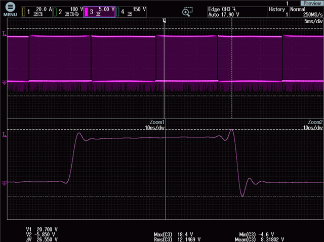
Problem 1: There may be spikes in the OUTA/OUTB pin drive pulse, especially when it is turned off. The downward spike is very large and lasts for about 5ns. The specification states that it is within 200ns, and -2V is allowed. Can you help confirm if there is a risk of -5.85V if this time is very short? What is the evaluation standard at this time?

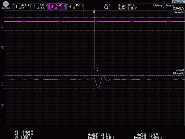
Problem 2: At the time of the drive shutdown, there is a fluctuation in the voltage of VDD-VSS, with the minimum value reaching 11.25. If the time is ns, please help confirm if there is any risk. What are the evaluation criteria?

Problem 3: When the drive is turned off, there is a large current spike on the VSS, with a peak value of approximately 300mA. Please help confirm what the internal circuit logic diagram of the chip driver pin is and how the current spike is formed?

Best regards,

Zhixia Bai

  • Hi Zhixia,

    1. What is the bandwidth of this oscilliscope measurement? Are you sure that the overshoot and undershoot are not just an artifact of measuring an edge rate with a limited bandwidth? The falling edge is faster due to the higher sink current.

    2. By shutdown, do you mean the driving enable low? If there is ripple on the power supply, you might want to add another decoupling capacitor to the supply rail. a 10nF+100nF pair should be able to eliminate this small ripple frequency. However, I don't think it poses a risk to the device or the system.

    3. The output is a CMOS inverter. When the low-side NMOS is closed, all of the gate capacitance is discharged from the output into VSS. This spike is the RC discharge current of the gate.

    Best regards,

    Sean

  • hi,

    1. he bandwidth of this oscilliscope measurement was 20M Hz, if it is appropriate?

    2.we had added a 1uf capacitor to the supply rail ,the capacitor should be used voltage stabilization,not high frequency filtering, why you advised 10nF+100nF ,otherwise ,why you thohght there was no risk ,what the standord of judging is;

    3.if there was detailed block diagram to help understand  

    ths.

  • Hi Zhiguo,

    The falling edge is faster than the 20MHz measurement bandwidth. You will see a Fourier series approximation of the real signal. This undershoot you observe should decrease with a higher bandwidth measurement. 

    Voltage stabilization and high frequency filtering are the same thing. I advise a 10nF+100nF since it will allow you to place a physically smaller, 10nF capacitor closer to the unit, which will lower the inductance of the supply decoupling. However, a 1uF is often sufficient unless extremely high transients make its parasitic ESL a limiting factor. 

     Here is a Texas Instruments decoupling capacitor report that I found for your reference: https://www.ti.com/lit/an/spra906/spra906.pdf

    Best regards,

    Sean

  • Hi Sean

    "This undershoot you observe should decrease with a higher bandwidth measurement."  means i change a higher   bandwidth?  eg. 50MHz?  

    and my initial question was that if there was risk when the OUTA/OUTB‘s  undershoot was -5.85V lasting 5ns  

    pls help confirm if i used 1uf could replace the 10nF+100nF pair which you advised

    i am so appreciated for your kindly help.

  • Hi Zhiguo,

    A 1uF capacitor is great. Yes, with a 200MHz oscilloscope bandwidth, the observed undershoot should go away.

    There is a risk if you pull the output too far negative, but there is an internal 2W ESD diode on the output to prevent this from happening. It will require a lot of current and negative voltage to damage the output of this device.

    But this is just an inaccurate measurement, not a true negative transient.

    Best regards,

    Sean