This thread has been locked.

If you have a related question, please click the "Ask a related question" button in the top right corner. The newly created question will be automatically linked to this question.

UCC27712-Q1: Rrising time & fall time

Part Number: UCC27712-Q1
Other Parts Discussed in Thread: UCC27712

I am confused that its 10% to 90% parameter for Vgs or Vds in data sheet?

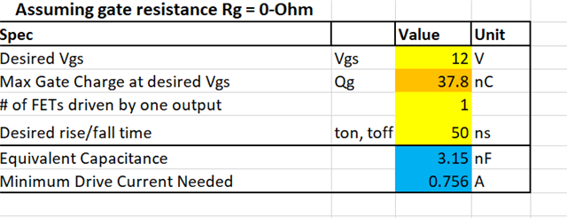
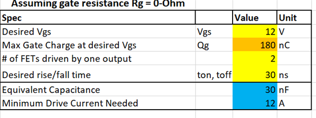
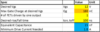
I use the tools to caculate the half bridge gate driver minimum current.  The disired rise/fall time is the same as the above parameter?

  • Hey Kevin,

    Thanks for your question.

    The 10%-90% parameter is the level of Vgs, for example it takes tRISE time for Vgs on the rising edge to go from the level of 10% to 90% of Vgs. So, in your case with 12V, the tRISE time is from 1.2V to 10.8V.

    For the Desired rise/fall time in the calculation table, you could run two separate calculations for source and sink current. Here is a quick calculation that I did based on your parameters for both rise and fall (source and sink) conditions.

    Rise: (max and typical times)

    Fall: (max and typical)

    Let me know if you have any further questions.

    Thank you,

    William

  • Hi William,

    thanks for your help! That help me a lot.

    now the customer need drive another power MOSFET IRF4668. I use tools to calculate as followed.


    the Minimun drive current is too high.  When I choose gate driver, I want chose high peak output current and long Trise. 

    But the Fsw=150KHz, I am confused how long Trise will not affect the Fsw. Can you promote a suitable gate driver. Thanks.

  • Hey Kevin,

    Are you trying to drive two of these large FETs in parallel? You have two FETs per output selected in the calculation. If it is just one of them, drive current is reduced to 6A which is more manageable. We do not have a driver that is in the 600V range that supports these high currents. UCC27714 has a drive current of 4A but is not automotive (Q1) rated if that is needed. With these higher drive currents, by using a the UCC27712, the rise/fall times will slow down to match the output of the driver of 1.8A source as seen here below for example.

    With the high current and high switching frequency, it may be of concern to look into power and heat as this could become an issue. A potential solution for driving this high current of 6A or 12A is using a BJT buffer to help source these high currents needed for this MOSFET.

    Let me know if there are any further questions.

    Thank you,

    Wiiliam