This thread has been locked.

If you have a related question, please click the "Ask a related question" button in the top right corner. The newly created question will be automatically linked to this question.

UCC27517A: Output signal ringing

Part Number: UCC27517A
Other Parts Discussed in Thread: UCC27517

Hello all,

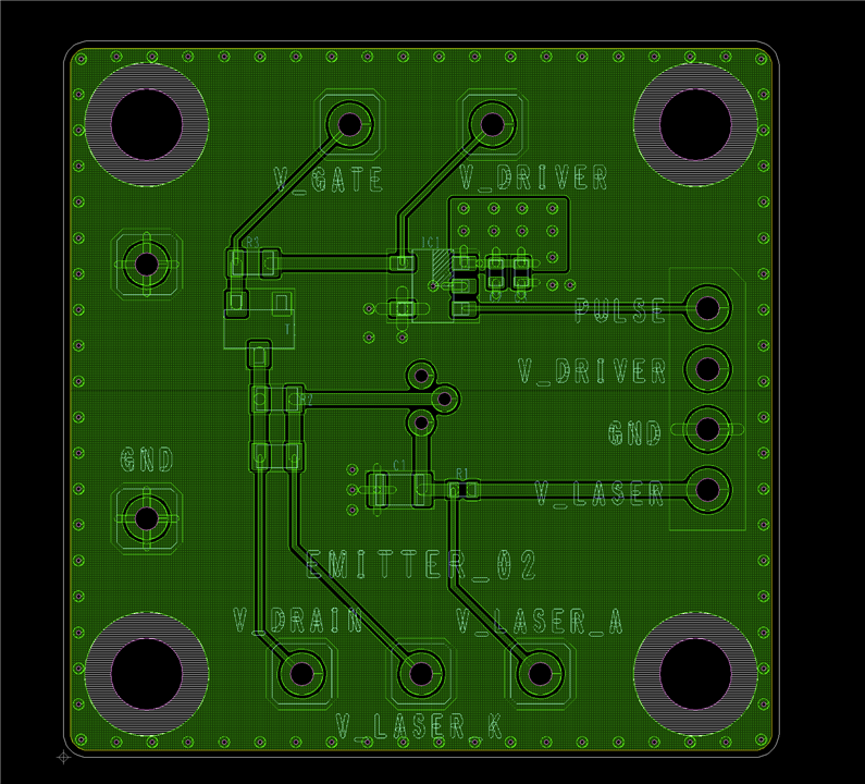
I have designed a simple circuit to turn on/off a MOSFET using the UCC27517 gate driver. The schematic is below.

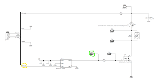
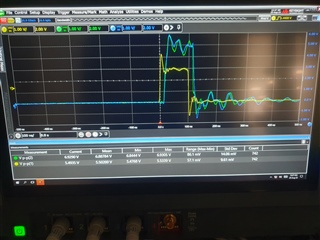
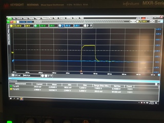
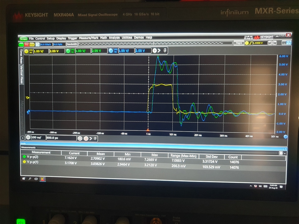
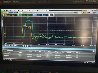
Using a waveform generator, I am applying a pulse signal with a width of 100ns at the Pulse input. Then, I am supplying the gate driver with 5V (although the schematic says 12V). However, at the output of the driver, the signal is ringing, as the image below shows. The waveform in yellow is the Pulse signal and the waveform in green is the driver output (the colours are also represented on the schematic).

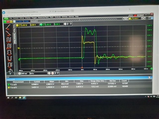
The main goal was to use a pulse width of 20ns but the output signal is even worse. Could the cause of the ringing be the overshoot and undershoot of the pulse signal from the Waveform Generator? Or is it another problem?

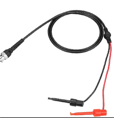
I do not know if this helps, but I am using these cables on the Waveform Generator.

Thank you in advance.

Best regards,

João Rego

  • Hi João,

    Typically, the output signal ringing isn't related to the input signal. Output ringing is usually dependent on how fast the current is being driven through the output stage, which can be affected by parasitic inductances. You can damp out the ringing by slowing the current drive with an external gate resistor, which I see you have in your schematic. I also see that you probed the output right before the resistor, so the output shown is undamped. Try probing after the resistor and see what the results are.

    Thanks,

    Rubas

  • Hi Rubas,

    After the resistor, the signal is still ringing. The blue waveform (image below) is the signal at the MOSFET gate (after the gate resistor).

    I inserted a damping resistor into the pulse coming from the signal generator and this is the waveform that I have got after the resistor (yellow waveform). As soon as I turned on the driver supply, the ringing appeared again at the driver output (both before and after the resistor).


    If helps, I will share my layout. On the image below is the bottom layer, where most components are placed (only the laser is on the top layer) and all the traces are. The top layer has only the laser (as I have already mentioned), the 2nd layer is power (driver supply) and the 3rd is GND.

    Thank you.

    Best regards,

    João Rego

  • After some research, I found that the problem might happen because of the long GND lead of the probe connected to the oscilloscope. So, I removed the long lead and I made a shorter GND connection on the probe with the blue waveform (signal at the MOSFET gate). As you can see in the image below, the ringing disappeared at the MOSFET gate. I also measured the other signals with a shorter GND lead and the ringing was also gone. Since I can only make one shorter GND lead during each measurement, the other signals will appear to have a ringing in their signal at the oscilloscope window (although in reality is just the GND reference that they have).

    Thank you.

    Best regards,

    João Rego