This thread has been locked.

If you have a related question, please click the "Ask a related question" button in the top right corner. The newly created question will be automatically linked to this question.

TPS61040-Q1: TPS61040-Q1

Part Number: TPS61040-Q1
Other Parts Discussed in Thread: TPS61040

Hi Team,

I have some queries on the TPS61040-Q1 IC.

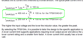
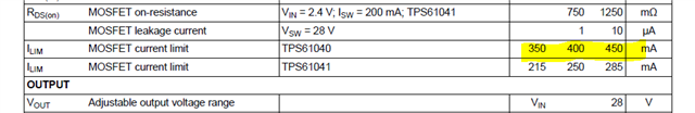
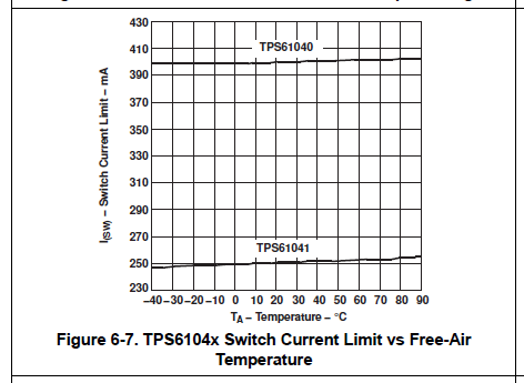
1. What is the max. load current support by TPS61040-Q1 IC?? In datasheet, I saw  Ilim = 450mA (MOSFET current limit) and Switch current limit is 400mA.

2. Will this IC supports 400mA or 450mA??

3. In my application, If my load current 500mA upto 200usec and normal load current is 50mA then will this IC supports or not??  Is any impact on the IC output voltage??

Thanks & Regards,

Giridhar N.

  • Based on the above equation,

    I got peak current is 455mA. (L= 10UH, Vin = 5.3V to 5.5V)

  • Hi Giridhar,

    The max output Iout of TPS61040-Q1 dependents on the inductor and the Vout. What's the Vout in your application?

    In datasheet, the min and typical MOSFET current limits are 325mA and 400mA, respectively. And the 325mA is the guaranteed current limit.

    Please note that this is the limit of the switching inductor current, not the output current.

    For a rough estimation with 40% inductor current ripple ratio and 90% efficiency, the max Iout = 1590mA/Vout.    

    Regards

    Lei

  • Hi Lei,

    I am using TPS61040-Q1 IC for generating 18.1V output.

    MOSFET current limit based on the datasheet is 350mA to 450mA and Switching Inductor current limit is 400mA

    Based on the Switching inductor limit, Min. output current is 240 mA (i considered inductor ripple  40% ==> 400mA  * 40% = 160mA ) .

    Calculations :

    Inductor current =400mA;

    Ripple =40%

    Min. Output current  = 400mA -400mA*40% =240mA

    Max. Output current = 400mA + 400mA*40% =560mA

    Is the above Correct??

    1. Do i need to consider the Inductor or MOSFET current limit for calculating the BOOST IC output current??

    2. Will this IC support transient response?? (like 500mA upto 200 usec) How much current will support??

    3. Will I out support 1590mA??

  • Hi Giridhar,

    I think the datasheet you referred is TPS61040, not TPS61040-Q1, please click here for the datasheet.

    There are some differences between the two datasheets, for example, the MOSFET current limit.

    You calculation is not correct. Please see my comments below:

    • Usually the saying of "switching inductor current limit" equals to the the "(Low-side) MOSFET current limit". They are  not the output current.
    • When calculating the max Iout, we should use the min MOSFET current limit(325mA), which is guaranteed.
    • Here is a rough estimation for the max continuous Iout. Suppose 40% inductor current ripple ratio and 90% efficiency are used.
      • Input current * 120% = Min MOSFET current limit, then Input current = 325mA/1.2 = 270mA.
      • Max continuous Iout = Min Vin * input current * efficiency / Vout = 5.3 x 270mA x 0.9 / 18.1 =  71mA
      • Please ignore my calculation in last reply, the above one is more accurate.

     Based on your description, the Iout is a pulse load with high level of (up to) 200us 500mA, and low level 50mA. What's the low level duration of 50mA?

    When the high level pulse of 500mA coming, the needed input current will much bigger than the MOSFET current limit, so the Vout will be pulled down. Suppose the Cout is 47uF, there will be a 2.2V Vout drop. After the 500mA pulse, then Vout will be recovered gradually. Whether it will be back to 18.1V depends on the duration of the low level pulse.

    Just let me know if you see any concerns.

    Regards

    Lei 

  • Hi Lei,

    Thank you for the response.

    In my application,  my load current consumption is 500mA < 200usec and min load is 30mA is continuous current.

    • Is above calculation applicable for the all BOOST converters (like above IC)??
    • How much time boost converter will take to stable the output again 18.1V??

    Regards,

    Giridhar N.

  • Hi Giridhar,

    For the boost with peak current control mode, yes you can refer to the following ways to estimate the max continuous output current.

    • Input current * 120% = Min MOSFET current limit, then Input current = 325mA/1.2 = 270mA.
    • Max continuous Iout = Min Vin * input current * efficiency / Vout = 5.3 x 270mA x 0.9 / 18.1 =  71mA

    For the pulse current load, you can estimate the Vout drop during the pulse high based on the total charge extracted out of Cout.

    Back to your case, the rough estimation for the time needed to make the Vout back to 18.1V is:

    • T_recover = Cout * Vout drop / (input current * (1-D) * efficiency - Iload) = 47uF * 2.2V / (270mA * 5.3/18.1 * 0.9 - 30mA) = 2.5ms

    That's means, the time interval between two 500mA pulse high is at least 2.5ms so that Vout can recover to 18.1V.

    Regards

    Lei 

  • Hi Lei,

    Thank you for the reply.

    The above feedback is resolving the my issue.

    I have one more question. In Datasheet, suggested Cout value is 1uF.

    • Is it ok to use 47uF capacitor at output?? Any impact on the operation (transients, load and line regulations) of the IC??
    • Where can i find the above equation? Is there any application note available??

    Thanks & Regards,

    Giridhar.

  • Hi Giridhar,

    The 1uF Cout is for the general applications. For your case, the big Cout of  47uF is used to prevent a large Vout drop when the 500mA pulse is coming.

    Vout drop = Pulse high level(500mA) * pulse duration(200us) / Cout.

    I attached one waveform for your reference, the condition is Vin=5.3V, Vout=18.1, Cout = 48uF, Iout pulse high =500mA, 200us, Iout pulse low =30mA, 4.5ms.

    You can see that when the Iout pulse coming, the Vout drops from 18.1V to 16.1V, and it takes around 3ms to recover to 18.1V.

    There should be no concerns to use the 47uF Cout.

    Regards

    Lei