This thread has been locked.

If you have a related question, please click the "Ask a related question" button in the top right corner. The newly created question will be automatically linked to this question.

UCC20225A-Q1: Sensored Brushless DC Motor Back EMF Problem

Part Number: UCC20225A-Q1

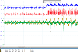
I am working on the current control of a BLDC motor with a speed of 12000rpm. The current controller in the system is designed as PI. I give a reference value of 10A to control the motor and the current controller can follow this reference value within a certain tolerance. When I apply a -10A reference to the BLDC motor, I apply a hard braking and the voltage value feeding the motor increases due to the reverse EMF. I try to burn this rising voltage on the load resistors. However, although I give -10A reference, the instantaneous current value passing through the motor phases rises up to 70-80A levels, and this rising current value damages my mosfets that provide commutation. Can you help me for the problem and solution suggestion here? (I share the Picoscope views with you. The blue signal is the power supply that feeds the motor, the red signal is the mosfet trigger signal that I switch to burn the back emf in the load resistors, the green signal is the current passing through the A phase of the motor and the yellow signal is the current passing through the B phase of the motor)

  • Hi Gökcehan,

    Is this for an electric aircraft propeller? 12kRpM is fast! Are you using InstaSPIN for a torque controller? 

    When I designed a propeller inverter, it was directly connected to a 8p 25R battery pack, which is able to absorb 35A of braking current without rising 50% like this. 

    It does not appear to me that the control loop is tuned to correctly control the -10A. It looks like there is some reactive power sloshing around. I understand the frustration of taking 2 hours of replacing FETs to try another test, but did you try starting with a less aggressive braking current target of 1 or 2A? You should also be able to implement a reduced edge rate from 10A to -2A, to help avoid overshoot (and instability) in the control loop.

    I don't know that this is a problem with our UCC20225A-Q1 gate driver. You may want to tag the C2000 group for more detailed support, if you are using one of TI's microcontrollers and InstaSpin.

    Best regards,

    Sean