This thread has been locked.

If you have a related question, please click the "Ask a related question" button in the top right corner. The newly created question will be automatically linked to this question.

BQ2970: Problem with initial "bootstrap"

Part Number: BQ2970
Other Parts Discussed in Thread: CSD85301Q2

Hello fellows,

I'm in the middle of testing this Li-Ion charger / protector, as schematic here:

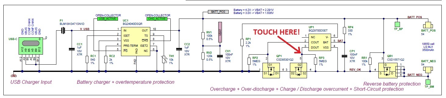
The problem is that the BQ29700 doesn't start in battery mode (QP1-2 doesn't trigger), unless I attach the USB-C charger OR touch with a finger the connection between UP1 pin3 and QP1 pin5 (gate), as noted in the schematic.

What would you suggest to fix that problem? 

Thank you in advance

md

  • Hi Marco,

    Sometimes, when the battery is connected for the first time, the discharging circuit is not enabled, and the V- pin must be shorted to the VSS pin, or a charger must be connected between PACK+ and PACK- to address the issue.

    Best,

    Andria

  • Hi Andria and thank you for your answer.

    Yes, I was aware of that.

    But there's another problem: after the rest of the circuit has been powered up (by connecting a charger or "touching" the gate), sometimes QP1 MOSFET opens again, thus turning off the entire board; if I keep my finger on the magic point, everything works correctly. Seems like a "lack" of a pull-down resistor... don't know what to do

  • Hi Marco,

    I don't think touching your finger to the gate of the DSG FET is having a pull-down resistor effect like the 5MOhm resistor.  The 5MOhm resistor is placed between the gate and source of the FET to help discharge the gate capacitance.  If anything, increasing the pull-down effect on the gate of the FET would keep the FET OFF, not turn the FET ON.

    To help troubleshoot your issue, I would like you to probe the DOUT pin to see if:

    1. The DOUT pin is ON during the FET opening--is it attempting to provide a HIGH voltage signal to the gate of the FET?
    2. There is noise in the system.  There is a possibility that your finger is having a capacitive effect on the circuit and helping with noise.

    A general rule of thumb: if your finger is wet, it is adding resistance, and if it is dry, it adds capacitance.(:

    Best,

    Andria

  • Hi Andria,

    further testings showed that there was some faulty connections on the programming/testing rig Disappointed - now the bq29700 + related MOSFETs seems to work as expected.

    But another problem appeared: the OCD (discharge overcurrent protection) is jumpin' in too much, cutting the power to the microprocessor and causing a reset; I saw that there's a lot of bq297xx variants, how can I choose the one with the desired OCD current limit? I've taken a look at the datasheet but it's very complicated, there's no magic formula to pick the right chip based on OCD current?

    Best,
    marco

  • Hi Marco,

    I am glad to hear that you discovered the cause of the issue!

    If you let me know what threshold values you are looking for, then I could help recommend a device.

    Best,

    Andria

  • Hi Andria,

    I need a OCD current limit of about 2.0A, 3.0A and 4.0A (three different devices).  Battery is a single Li-Ion 4.2V.

    Thank you,

    m

  • Hi Andria,

    after several testings, the board's only problem is the bq29700 that's cutting connection when the current consumption rises.


    Please give me some advice to choose the best bq297xx version depending on requested current (2, 3 and 4 A - a formula will be appreciated), let me know if you need some other parameters.

    Best regards
    md

  • Hi Marco, 

    Since the BQ2970 measures the voltage drop across the protection FETs, all current thresholds listed in the device comparison table will be voltages.  Here are the steps for determining your threshold value:

    1. Determine your maximum desired discharge current (Idmax)
    2. Ensure that the discharge overcurrent circuit does not trigger until the discharge current exceeds Idmax.
    3. The total resistance tolerated across the two external FETs (CHG + DSG) should be OCD / Idmax = total ON resistance
      1. Note that OCD variable listed in this equation will be the OCD threshold you are looking for.
    4.  Based on the information of the total ON resistance of the two switches, determine what would be the OCC threshold based on your maximum charge current (Icmax).
      1. total ON resistance × Icmax = OCC
      2. Select a device with an OCC threshold at or slightly above the calculated OCC.

    Hopefully this helps!

    Best,

    Andria

  • Hi Andria,

    thank you very much for your detailed and clear explanation!

    Just to check out, using the CSD85301Q2 MOSFET as in the schematic:

    Total MOSFETs resistance (at Vgs = 2.5V, the worst case in my circuit) = 0.033 x 2 = 0.066 ohm

    at Ids = 3A: V = 0.066 x 3 = 0.099 V  <-- only 1 mV below bq29700 threshold!!! here's the problem!!!

    I'll try to change the bq29700 with a bq29702 (OCD threshold = 0.160V) and post the results here.

    BTW, there's no difference between bq297xxDSER and bq297xxDSET except packaging, right?

    again, thank you!

    Marco

  • Hi Marco,

    Yes, I would recommend re-attempting the circuit with a device that has your desired thresholds to avoid triggering any faults and protections. 

    The difference between the R and T is reel vs. tape.  Each has a different minimum order quantity, so please note this (reel is higher MOQ and lower cost, typically). 

    Best,

    Andria

  • Hi Andria,

    just a quick note to confirm that everything now works correctly with a bq29702 (higher discharge current limit than bq29700).

    Thank you very much for your assistance, best regards

    md

  • Hi Marco,

    Thanks for the update, and best of luck with your overall project!

    Best,

    Andria