Other Parts Discussed in Thread: UCC28070,
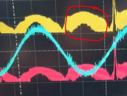
Dear Sir, I have designed the 1 KW Interleaved Boost PFC Converter using UCC28070. I am attaching the schematic of the design. I am facing the problem while running it. I am not been able to get the output voltage. While examining the outputs, I found that one of inductor current's waveform is not proper. I am attaching the picture of that inductor current. I swipe the inductors and also change them with new ones. But the shape of inductor 2's current on that phase is same. It goes to that shape when I was crossing 80 input voltage. On the other hand, Inductor 1's current is good at 80 Voltage.
Inductor 2 is making noise and flowing abrupt current as I shown in picture whenever I cross the 85 voltage. I am not been able to cross 85 Voltage to get output.
Please let me know what should I do. 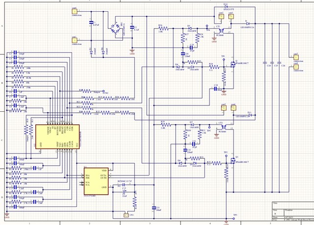


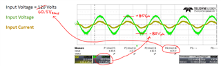
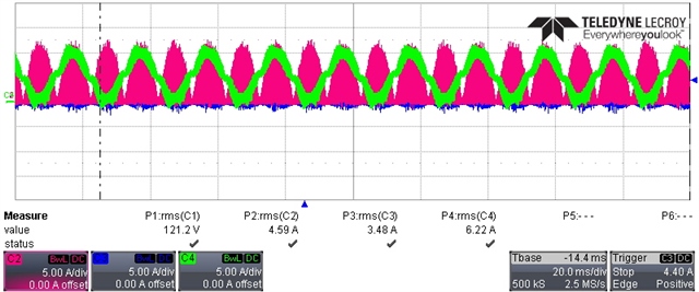 At 120 Input Voltage
 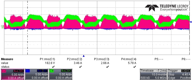 At 180 Input Voltage
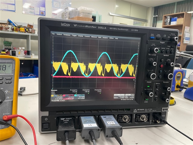
 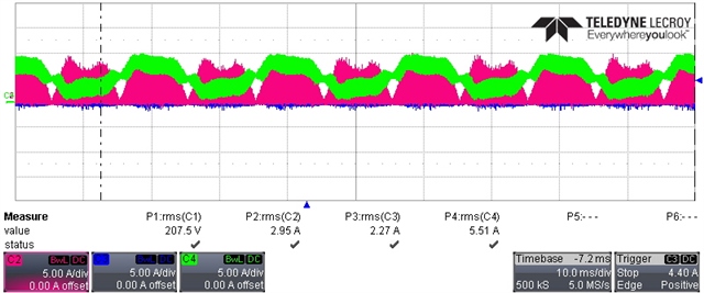 At 210 Input Voltage