This thread has been locked.

If you have a related question, please click the "Ask a related question" button in the top right corner. The newly created question will be automatically linked to this question.

TPS65987DJEVM: USB-C DP1.4 Sink Demo Config with 10G-EXPANSION (HD3SS460)

Part Number: TPS65987DJEVM
Other Parts Discussed in Thread: TPS65981, , TPS65987D, HD3SS460, TUSB1064, TPS65987DDJ, TPS65987DDK, TPS65987
Hi!

I am attempting to get a working demo going for a DP1.4 sink and 100W PD source Type-C UFP for use in a docking application. I have a TPS65987DJEVM and managed to get one of the (discontinued) 10G-EXPANSION kits. From reading a few other forums on TI E2E, it sounds like the default UFP demo for the TPS65987D___ in the "TPS65981_2_6_7_8 Application Customization 6.1.3 tool" should work. However, I am not able to receive a DP1.4 stream from my laptop. I haven't focused on the 100W PD source part yet; I need to get DP ALT mode working first.

I'm using the DisplayPort Sink expansion board, and I am providing external power via an OTS charging brick. I see that the HPD LED indicator, as well as power LED indicators are on.

I then took a closer look at the default UFP demo and noticed that the crosspoint/de-mux control signals look more suited for the TUSB1064, but the 10G-EXPANSION DisplayPort Sink card looks like it has a HD3SS460 (I don't have schematics or a user guide for the expansion card). From the datasheets of these parts, it looks like the TUSB1064 is expecting FLIP, CTL0, and CTL1 control signals, while the HD3SS460 is expecting POL, AMSEL (3-level), and EN (3-level) control signals. I then visually followed the traces on the 10G-EXPANSION and compared them to the pinout on the B2B connector and the TPS65987DJEVM schematics to find that that:

TPS65987D GPIO0 <-> SSMX_DP LED <-> HD3SS460 EN

TPS65987D GPIO1 <-> SSMX_FLIP LED <-> HD3SS460 POL

TPS65987D GPIO2 <-> SSM_USB LED <-> HD3SS460 AMSEL

I tried modifying the default UFP demo as follows, and was able to receive a DP1.4 sink stream, but only with one USB-C cable orientation.


Could you help me configure this demo properly? Or at least provide a working .pjt or .bin file so that we can get a working demo going and move on to schematic capture. We will likely use the TUSB1064 instead of the HD3SS460 because it has a redriver, but we would still like to get a working proof-of-concept before selecting the TPS65987D for our application.
Thank you!
-Peter
  • Peter,

    Seems like you are trying to use TPS65987DDJ with project file for TPS65987DDH. These are two different ROMs and you cannot mix and match. You may need a TPS65987DDK. Can you reach out TI local sales, as TPS65987DDK is not available on TI.com.

  • Hi Ghouse,

    Thank you for the prompt response!

    To clarify, I am using the TPS65987EVM (it looks like this is the only flavor of this EVM available). Based on both the user's guide and schematics downloaded from the TI page, the EVM has the TPS65987DDH on it, which is why I chose that part for the configuration software.

    If the EVM has a different PN, can you send me updated schematics to match - unless that is the only difference?

    Thank you,

    -Peter

  • Hi Peter,

    We have both TPS65987D and TPS65987DDJ EVM on ti.com. Can you please confirm which one you have?

    Can you also please send me your current project .pjt file?

    Best,

    Alex

  • Hi Alex,

    Ah, I didn't realize there was the TPS65987DJEVM as well! I'll order one just in case we need it.

    But confirmed, I have the regular TPS65987DEVM with the TPS65987DDH on it. Apologies for the wrong P/N in the title!

    I've attached my pjt file.

    Thank you!

    -Peter

    TPS65987DEVM_10G_EXPANSION_SINK_DEMO.pjt

  • Hi Peter,

    Please refer to figure 4 on page 13 of this Display Port application note for information on how to properly configure the GPIO events to control the HD3SS460 part. You can also look at other pages to see if display port capabilities register and other settings match up correctly with your project.

    https://www.ti.com/lit/an/slva844b/slva844b.pdf?ts=1695073491300&ref_url=https%253A%252F%252Fwww.ti.com%252Fproduct%252FTPS65987D

    It does look like you are using the correct GPIO events. Can you try the UFP w HD3SS460 configuration settings in the document and see if it works?

    Best,

    Alex

  • Hi Alex,

    Thank you for sharing this app note. However it was this app note that I followed in the first place to configure this demo.

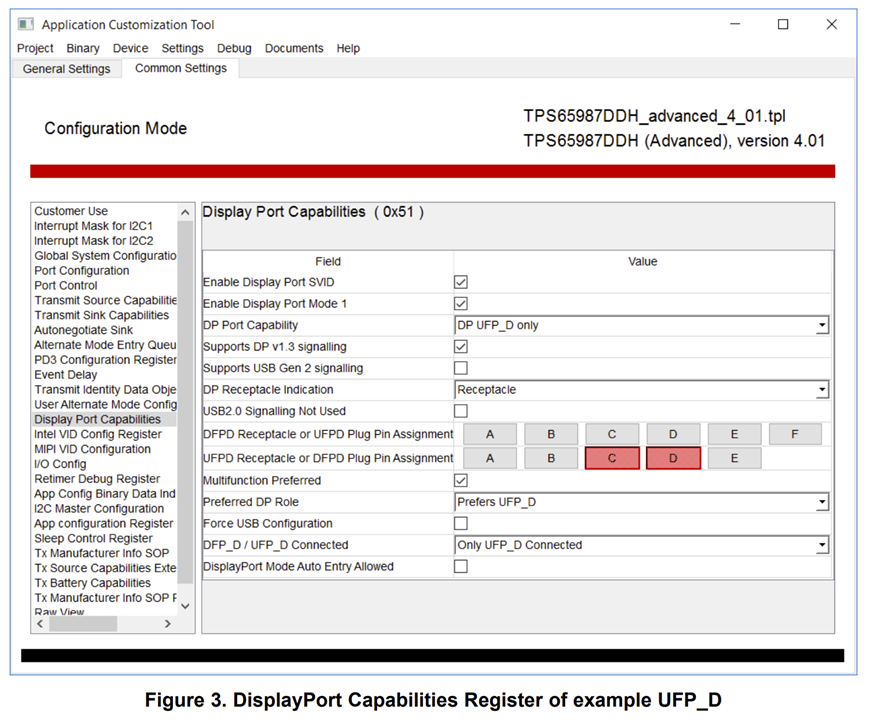
    Still no luck. The displayport alt mode only works with one Type-C cable orientation. Based on that same app note, it looks like I should configure the UFPD Receptacle to E only? Is that correct?

    Thanks,

    -Peter

  • Hi Peter,

    You can enable UFPD Receptacle pin assignments C,D, and E. Enabling more pin assignments than needed is ok, the pin assignment will be set based on the type of cable connected and 2-ch/4-ch DP. Also, please try setting the "DisplayPort Mode Auto Entry Allowed" bit in the GUI.

    I confirmed that this is correct:

    TPS65987D GPIO0 <-> Port 0 DP or USB3 Event <-> SSMX_DP LED <-> HD3SS460 EN 

    TPS65987D GPIO1 <-> Port 0 Cable Orientation Event <-> SSMX_FLIP LED <-> HD3SS460 POL

    TPS65987D GPIO2 <-> AMSEL Event <-> SSM_USB LED <-> HD3SS460 AMSEL

    Your GPIO configurations are confirmed to be correct. The reason for the DP alt mode only working with one orientation would likely be due to the SSMX_FLIP signal (HD3SS460 POL and TPS65987D GPIO1) which is driven by the Cable Orientation Event. You can try adding wires to these signals on the EVM to probe them and verify they are working on your board.

    It was good to see you were able to get one orientation to work. This confirms that the issue is only with the cable orientation signal. One other thing to note is that the 10G expansion boards for DP sink/source are not the most reliable (part of the reason why they were discontinued). There might be an issue with the board that causes it to work only for one connection orientation. That being said, if the signals coming out of the TPS65987D are correct on GPIOs 0, 1, and 2, the MUX will be programmed correctly and DP should work. I do not expect to see an issue on an actual board design, without the 10G expansion header.

    Best,

    Alex

  • Hi Alex,

    Understood, thank you. We will continue prototyping.

    Thank you!

    -Peter