This thread has been locked.

If you have a related question, please click the "Ask a related question" button in the top right corner. The newly created question will be automatically linked to this question.

UCC28180: TIDA-010081

Part Number: UCC28180
Other Parts Discussed in Thread: TL431, UCC28064A, UCC28050, UCC2818, UCC28056, UCC28065, UCC28070A

Hi ,

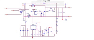
I have implemened 1kW PFC stage as AC to DC with PFC Operation and its working good.

in my output 100HZ ripple component comes as 5 to 15V.

Kinldy help,me to get rid of this 100HZ component traveling through output,do i need to adjust voltage loop?

advice me what to change?

Thankyou,

venkatesh

  • Hello Venkatesh, 

    Thank you for your interest in the UCC28180 PFC controller. 

    Your PFC design is working correctly.  The 100Hz ripple on the output is a normal part of all PFC designs.
    You would not achieve high PF without it. 

    The purpose of power factor correction is to reduce the distortion of the AC line current as much as possible. 
    When the input AC voltage is at the zero-crossing, the current should also be at the zero-crossing. 
    When the input AC voltage is at the peak, the current should also be at the peak. 

    At the line zero-crossing, no power can be delivered to the output so the load on the PFC draws down the output capacitor voltage. 
    At the line peak, lots of power can be delivered to the output so the PFC can support the load and also build up the output capacitor voltage.
    The net result is a ripple voltage at twice the line frequency.   

    The voltage control loop bandwidth is deliberately reduced below the line frequency (typically ~10Hz cross-over) in order to avoid regulating out this ripple voltage.  
    If you increase the BW to regulate the voltage for lower ripple, the input current will become extremely distorted when it tries to pull in high current while the input voltage is low. 

    The normal amount of peak-to-peak ripple voltage is about 5% of the average Vout at full load.   So for 400Vdc average output, ripple = 20Vpk-pk, or +/-10V. 
    The pk-pk ripple diminishes as the load becomes lower. 
    The only other way to reduce Vpk-pk without increasing V-loop BW is to increase the size of Cout.  This can become expensive and increases volume of the PFC stage. 
    But it is usually not necessary to remove the ripple, since most down-stream DC/DC converters are designed to easily accommodate a little variation of their input voltage.  

    If you try to reduce size and cost by under-sizing the capacitor and allow more ripple (such as 10% of Vout) you increase the risk that the ripple peaks will trigger over-voltage protection or other special responses from the controller.  I recommend to stick with a maximum of 5% of Vout at full load. 

    Regards,
    Ulrich

  • ok Thanks

    our requirement at output side is 59V,17A DC.PFC+LLC stage

    I thought of reducing at PFC output side,now it seems not possible there.Kindly let me know/direct me how to reduce 50HZ/100HZ ripple at output side.

    Our Ripple at output side is 0.5VPk to pk & 0.5A pk to pk

    waiting for your advice

    Thank you

    venkatesh B

  • Hello Venkatesh,

    Are you saying that you are measuring 0.5Vpk-pk 100Hz ripple on your 59V output?  That is already less than 1% of the output voltage.  
    To reduce this ripple further, the voltage-loop frequency response gain of the LLC converter at 100Hz must be increased.  
    That is IF the output ripple is a consequence of poor regulation of the input ripple.  

    On the other hand, if the regulation reference of the LLC control is sitting on a GND that has 100Hz ripple current flowing through it (such as from the PFC output to the LLC input) then the GND voltage ripple may be being amplified by the LLC control. 
    Make sure that the LLC regulation control (very often (although not always) it is a TL431 type of regulator with opto-coupled feedback) is referenced to a clean quiet GND point with no switching currents flowing through it.    

    If the LLC regulator is already on a quiet GND, then probably the loop-gain at 100Hz has to be increased.  

    If you need further support on LLC issues using TI controllers, please start a new post so it can be routed to an LLC expert.   

    Regards,
    Ulrich

  • ok thanks,i will post separately.

    Kindly suggest PFC topologies which give High PF fir variable loads and wide input voltages please 

    Thank you

    venkatesh B

  • Hello Venkatesh, 

    The non-isolated boost topology is the most widely used topology for PFC and TI provides several controllers to choose from.
    All of them provide high PF at full load and low input line.  

    PF is combination of phase shift between input current and input voltage and total harmonic distortion of the current (THDi). 
    PF is usually very high (>0.99) at full load and low line, but drops off as load becomes lighter and line voltage rises. 
    This is because the line current becomes more distorted at low current (so THDi increases) and because the 90-degree current of the EMI-filter capacitance becomes a larger part of the total input current. 

    High power CCM PFC controllers include UCC28180, UCC28070A, UCC2818, and lower power transition mode PFC controllers include UCC28064A, UCC28065, UCC28050, UCC28056.  

    Regard,
    Ulrich