This thread has been locked.

If you have a related question, please click the "Ask a related question" button in the top right corner. The newly created question will be automatically linked to this question.

LMR51430EVM: Output Ripple

Part Number: LMR51430EVM
Other Parts Discussed in Thread: LMR51430

There are two questions about this EVM.

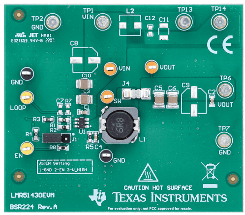
1. Why both C8 and C9 are not placed on the EVM as below diagram? on the EVM bom, it looks both has placed. 

2. Customer tried to test EVM without any component modified. the Vpk-pk is very high. Could you guide how to improve it efficient? thanks. 


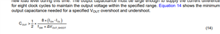
Dynamic Load Condition:

On time: 10mS

Off time: 5mS

S/R: 6A/uS

Test 1: 0.3A -> 2.5A, Vpk-pk : 807mV

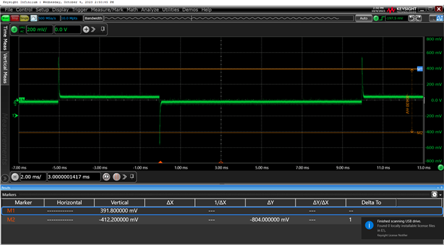
Test 2: 0.3A -> 3.0A, Vpk-pk : 1.07V (waveform is as below)

Here are more waveforms tested.

LMR51430EVM Test Waveform.zip

  • Hi Brian,

    The capacitors may not be populated if they are optional by the EVM design, but the pads remain to give the end user the option to add the components if they choose to.

    To improve the load transient response, increase the output capacitance. Section 9.2.2.5 of the LMR51430 datasheet provides more detail and an equation to calculate output capacitance for a specific Vout overshoot and undershoot: https://www.ti.com/lit/ds/symlink/lmr51430.pdf

    Best regards,

    Ridge Lahti

  • Thanks, output cap could play with stability and phase margin? However RD has added 100uF, there is no any change on overshoot/undershoot. 

    Is that possible improved by CFF capacitor connected with high side feedback resistor in parallel? What R/C value you suggeste to improve?

  • Hi Brian,

    The output cap does have an impact on stability and phase margin. Adding output capacitance can increase your phase margin. The CFF capacitor can improve load transient response. However, the correct value of capacitance depends on the bandwidth of the converter itself. You would need to determine the crossover frequency of the converter in order to calculate your starting point of CFF capacitance. From there, you would need to adjust in the lab until the desired overshoot is achieved. Here is a link to a useful application note on the topic: https://www.ti.com/lit/an/slva289b/slva289b.pdf

    Best regards,

    Ridge