A related question is a question created from another question. When the related question is created, it will be automatically linked to the original question.
If you have a related question, please click the "Ask a related question" button in the top right corner. The newly created question will be automatically linked to this question.
UCC28780: Dynamic Response for use in 60 Hz output Applications
I am interested in knowing if this controller can be used in AC output applications at 60 Hz. In other words, is it possible to modulate the reference voltage at 60 Hz to yield an AC waveform at the output.
You mentioned UCC28780 in your thread title. For the purpose of building a basic inverter, it seems UCC28780 has many off-line features you would not be taking advantage of - Can you explain more about what you are trying to achieve and why UCC28780 might be an option? Can you provide a block diagram around the UCC28780 showing how you envision it used in your inverter application?
The features within 28780 all seem to be very attractive to me. Voltage and current feedback controller, active clamp (very important due to high output power), etc. Notice that the input power is from a very stable DC source ( LiFePO4 battery system) that is at 55 to 61 V.
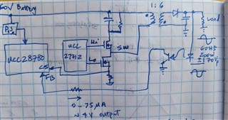
I am building a three-phase 200W/phase inverter at 120 Vrms per phase (i.e. 170 Vpeak) using a 6 to 1 turns ratio flyback transformer. I'd like to gang up three 28780s and synch them up together by providing three sinusoidal reference voltages, each at 120 degrees from the next. Also, I will be using GaN FETs which is another thing that 28780 offers me when used in conjuntion with UCC27712.
I will not be using Active clamping on the output voltage as the output voltage requirements are too high for active clamping.
As for the feedback, I am still pondering that but I think a reasonably linear CTR opto could work but I have plenty of other options here.
Please see the attached hand-drawn diagram as requested. I tried to attach a diagram here but to no avail...I will try to see if I can email it to you.
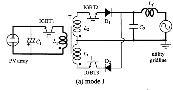
Thank you for sending the schematics. Regarding your configuration I have a few doubts on how AC signal would be produced. Although I have never seen usage of DC-AC topology using this IC, the following configuration seems more realistic from an inverter point of view.
In Mode I IGBT1 is at on-state with all other IGBTs in off and the stored energy in the capacitor is discharged to the ac utility grid line with the polarity of capacitor synchronized with that of the ac utility grid line.
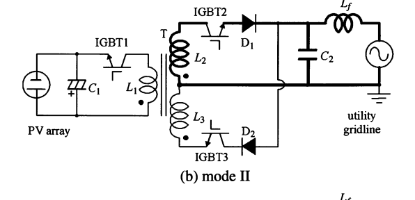
In Mode II IGBT2 is at on-state with all the rest in off, implying the stored energies in transformer and capacitor are being released to the ac ultility and giving the positive polarity. Modes I and II are switched alternately at high switching frequency during the positive half cycle.
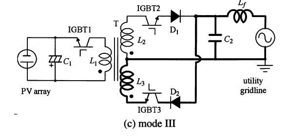
Mode III is for the negative half-cycle polarity. Mode I and III are switched alternately at high switching frequency during the negative half cycle.
My main concern is that the envelope of the peak current through the primary winding of the flyback transformer is to modulated by the pulsewidth modulated (PWM) gate pulse of IGBT1 to a sinusoidal form and to be in phase with the ac utility grid line voltage. This is going to be a challenge and we have limited experience in using this IC for such applications as it was designed primarily for offline AC-DC applications and recommended to be operated as a DC - DC power stage.
Thank you for copying some of diagrams and text from your textbook on power electronics in response to my inquiry.
I am disappointed that you didn't even make a basic attempt at understanding my design question regarding the 28780. To start with, there is NO GRID present in our design. We are simply generating an AC waveform at ~200W and 60 Hz. Your main objection seems to be the synchronization of the grid and the PWM the gate of our FET. This synchronization is not even a concern at this point.
I don't know where to go from here other that the fact that I need to communicate with someone that actually attempt to understand my question and not provide me with lecture notes from the first year power electronics class.
If I understand your pen sketch, is there a time varying low frequency signal (60Hz) at FB, so that Vcst/Vfb ratio will be continuosly modulated by PCC scheme and you should be able to produce sinusoidal voltage. For negative ac voltage you might need to add a DC offset to ensure that Vfb is within 0-4V scale which will probably result in a sinusoidal envelope with an offset due to unipolar operation of the flyback converter or maybe you might have a better approach of dealing with this as this is not explicitly shown in your pen sketch.
I am building a three-phase 200W/phase inverter at 120 Vrms per phase (i.e. 170 Vpeak)
My comment on synchronization is based on that as UCC28780 does not support this and reliable operation would require external synchronization of indiviaul controller modules which some of our other PFC/DC-DC controller support.