This thread has been locked.

If you have a related question, please click the "Ask a related question" button in the top right corner. The newly created question will be automatically linked to this question.

TPS23753A: Power dissipation

Part Number: TPS23753A

Hi I'm Jieun, 

I have a question about Power dissipation of TPS23753A

When 48V POE voltage is applied to VDD pin, how can I calculate the power dissipation?

Also, I would like to know the same, when DC 12V aux adapter voltage is applied to VDD1 pin

Power dissipation of TPS23753A when the power is applied

1) 48V POE 

2) DC 12V aux 

best regards,

  • Hi Jieun,

    Please see the measured power of TPS23753AEVM-004 (www.ti.com/.../TPS23753AEVM-004):

    48-V RJ45 input at open load condition: Vin = 48V, Iin = 14.03mA, Vout = 3.3V

    12-V VDD-RTN adapter input at open load condition: Vin = 12V, Iin = 21.91mA, Vout = 3.3V

    Best regards,

    Diang

  • Hi Diang, 

    Thanks for your reply, 

    When I see the TPS23753AEVM-004, I couldn't find the input current information.

    I was wondering if I could know the Iin value when the output voltage is 5V under the same input condition?

    And, if I calculate the power dissipation of TPS23753A, which value should I check in the datasheet?

    (under the same condition as I mentioned

    (1) 48V POE voltage is applied to VDD pin

    (2) DC 12V aux adapter voltage is applied to VDD1 pin)

    Best regards,

  • Hi Jieun,

    Thanks for your reply. 

    Normally 60 – 70% power loss comes from the DC/DC converter: the FET switching & conduction loss, snubber losses, gate drive circuit loss, transformer / inductor core & winding losses. These losses depend on the converter design. The TPS23753A's internal hotswap and power interface rectifier losses take <30% normally. The other losses such as quiescent current loss could be neglected for a rough estimation. 

    Assuming a 13-W PD input power and 48-V input from RJ45. I = 13W/48V = 0.27A. With a 0.7-Ω hotswap on-resistor, the internal hotswap power loss is 51 mW (less than 0.4% of 13-W total power).  The rectifier loss is 0.27A * 0.7V * 2 = 378 mW (less than 3% of 13-W total power). The rest is dc/dc converter loss.

    If using 12-V VDD-RTN adapter input, the hotswap is not conducting and there is no hotswap power loss and rectifier loss. There will be a additional oring diode loss (13W/12V*0.7V = 758 mW). The rest is dc/dc converter loss. While the converter may has lower efficiency consider the current will increase when voltage drops.

    Best regards,

    Diang

  • Hi Diang, 

    I want to estimate Tj data from below equation

    Tj = Tc + ψjc(℃/W) * W

    I could find ψjc(/W) value in datasheet, 1.9(℃/W) but, I have no idea how to get power dissipation of TPS23753A. 

    That is why I ask you TPS23735A's power dissipation in two cases. 

    1) 12V VDD-RTN adapter input

    2) 48-V input from RJ45

    Best regards,

  • Hi Jieun,

    Please see my comments:

    1) 12V VDD-RTN adapter input:

    - The controller operating current is 0.58 mA (typical value), the loss is VC * 0.58 mA

    - The power interface operating current could be neglected after handshake

    - If you have a VB load (I_VB load), in a VC-VB linear regulator, the loss is (VC - VB) * I_VB load

    - A certain percentage of the gate drive power loss: 0.5 * Cgs * VCC^2 * fsw

    2) 48-V 13-W input from RJ45:

    - hotswap power loss is 51 mW (0.27A, 0.7-Ω) 

    - The controller operating current is 0.58 mA (typical value), the loss is VC * 0.58 mA

    - The power interface operating current could be neglected after handshake

    - If you have a VB load (I_VB load), in a VC-VB linear regulator, the loss is (VC - VB) * I_VB load

    - A certain percentage of the gate drive power loss: 0.5 * Cgs * VCC^2 * fsw

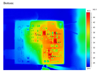
    Besides, you could check the Tj by the Tcase. Please find attached thermal image from (https://www.ti.com/lit/ug/tidudl1/tidudl1.pdf). The case temeprature is 46.6C at 48-V input at ~24C ambient temperature in natural convection. When with 12-V adapter input, the temperature rise could be similar or slightly lower consider no hotswap loss and less miller cap (Vdg) discharge voltage at turning on. 

    Best regards,

    Diang

  • Hi Diang, 

    Thanks for reply, 

    I have more question.

    - A certain percentage of the gate drive power loss: 0.5 * Cgs * VCC^2 * fsw

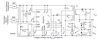
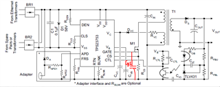
    From this equation, Is VCC voltage Vc or GATE voltgae? and what is Cgs from below circuit?

    Best regards,

  • Hi Jieun,

    Thanks for your reply.

    Cgs is the gate-source voltage of the M1 FET. Normally it is several hundreds pF to several nF for this application.  

    Vcc is the Vc voltage, since Vc is the positive rail of the gate drive for M1. 

    Best regards,

    Diang