This thread has been locked.

If you have a related question, please click the "Ask a related question" button in the top right corner. The newly created question will be automatically linked to this question.

TPS543320: inductor selection

Part Number: TPS543320

Good day, colleagues,

My customer is working on implementing TPS543320 device,

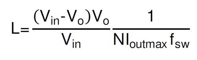
From datasheet readings and while analyzing inductor losses, they decided to go with 1000kHz for the 8A rails and 1500kHz with the 3A rails.

Can I get your opinion on three rails:

+3.3V_ENV: This is relatively low current with 2A limit selected. Is it possible to change to 2.2uH or is there an issue/drawback with this? (Current may become quite low <<1A…) 1500khz

+1.8V/+1.5V: Would you see an issue in changing the inductor from 1.5uH to 1.2uH if the current on this rail may decrease to 1…2A during running? Or is 1.5uH a better choice? 1500kHz

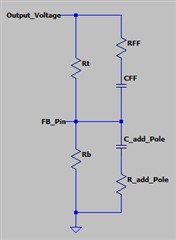
This is what they plan to implement on the PCB. What is a bit unknown is the effect of the capacitors at the loads – some distance to the DCDCs:

TPS543320-620-820_Calculator_RevB__20231010.pdf

Thank you,

Daria

  • Hi Daria,

    The inductor selection is decided by the limitation as follows:

      a. Inductor current ripple: If the inductance is too low, the inductor current ripple is too large, and the output voltage ripple will be too large.

      b. Loop stability: If inductance is too small/large, the loop may be not stable.

      c. Ensure the peak current under full load is below the over current limitation and the valley current under 0A load is higher than the negative over current limitation.

    So usually we choose inductance to let the inductor current ripple equal to N=20%-40% of max loading current. The inductance value can be derived as equation:

    It's ok to use 2.2uH inductor for 3.3V rail and 1.2uH inductor for 1.5/1.8V rail. The N is ~24% for both rail without any risk.

    Please let me know if you have further questions.

  • Hi Zhao,

    There is a comment in the datasheet on page 24 about adding an RC to the FB pin for higher ESR capacitors. As there is some resistance in the PCB routing, there may be a need to do so? (May look like higher ESR bulk caps added on the load end) Is this, how the divider should look like to account for this?

    (The add_Pole parts are spare for me to add another pole as needed)


    I wonder what happens if you have an LC output filter at lower frequency than on the demo with lower Q-factor. Does that improve the phase margin? Worst case in my test set up is to crossover closer to the LC-resonance.

    Thanks,

    Daria

  • Hi Daria,

    As there is some resistance in the PCB routing, there may be a need to do so?

    The ESR means the resistance in series of the output capacitor but related to the resistance in the PCB routing.

    The PCB routing may little impact the efficiency but wouldn't influence the loop, so if our customer is using MLCC capacitors, there's no need to add this Feedforward RC(RFF and CFF in your schematic).

    I wonder what happens if you have an LC output filter at lower frequency than on the demo with lower Q-factor. Does that improve the phase margin? Worst case in my test set up is to crossover closer to the LC-resonance.

    What's your point here using lower frequency LC filter? Do you plan to use larger L or C? I'm slightly confused. As I mentioned above, the inductor you choose is ok.