This thread has been locked.

If you have a related question, please click the "Ask a related question" button in the top right corner. The newly created question will be automatically linked to this question.

LM26420: No output from one of the 2nd DC-DC converter - SW pin is not showing stable output

Part Number: LM26420

Hi,

       I am working on board in which we have used LM26420 for 3.3V and 1.8V output with 5V input, the circuit is shown below

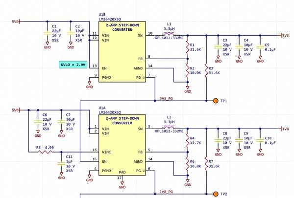
I am getting no output from 3.3V and therefore the 1.8V is also not working. 

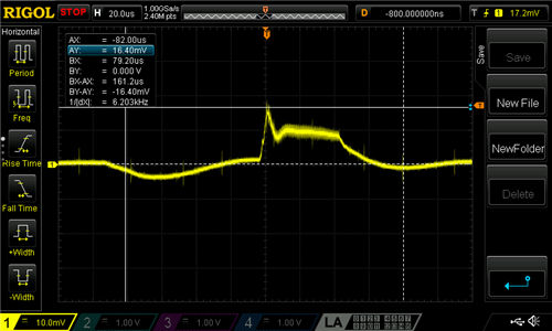
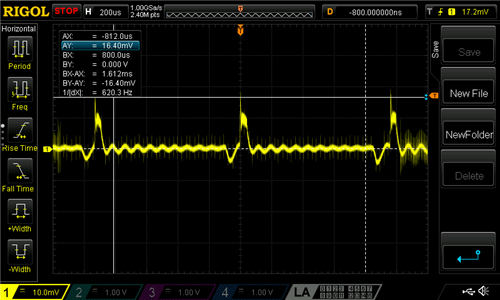
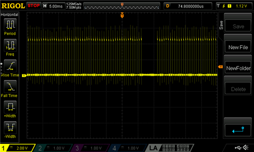
Also, if I measure with oscilloscope on the SW pin, I observe the following 


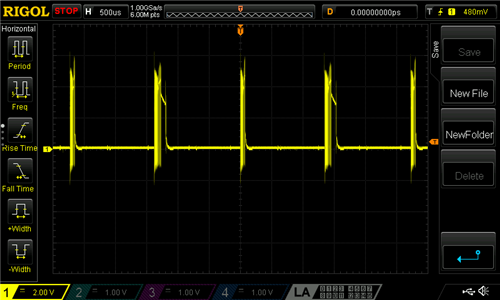
and if I remove the inductor from the circuit and measure SW again then 

Can you please help me with this?

Thank you

  • Hi Mohsin,

    Can you also add the inductor current to the scope shot (with inductor populated on board)? Can you check if the device is current limited by an overload condition on the output rail? You could disconnect all loads on the output and try. Did you also try swapping the unit with a new one to see if it due to a soldering issue?

    Best regards,

    Varun

  • Hi Varun,

             Thank you for your quick reply.

    I do not have the current probe so cannot measure the inductor current. I removed the inductor L1 (3.3V) and used an external bench supply for 3.3V, then I observed the PG_3V3 and it is coming as square wave. 

    I removed both inductors (L1 and L2) and used bench power supply for 3.3V and 1.8V and board circuit seems to work well. The current draw for 3.3V is around 0.5A and for 1.8V is 0.8A, which suggests that the 3.3V is not overload. 

    I have three boards and all have the same behaviour, could it be soldering issue or is it possible that these ICs are no good (damaged at manufacturer when assembling)?

    Any more suggestions will be appreciated. 

    Regards

    Mohsin 

  • Hi Mohsin,

    Would it be possible to add like a 100mOhm resistor in series with the inductor and measure the voltage on this resistor to check the inductor current?

    Are there any other bulk caps on the 3.3V rail? Just wanted to check, cause the device may find it hard to startup with large bulk caps.

    It could be the overload conditions on the rail are transient events, so it may not be visible on the DC current display of external power supply.

    Could you tell me what is the switching frequency you observe?

    You could check if the IC is damaged by looking for pin to pin shorts with the IC powered down. You should also be able to measure a diode voltage between GND and every other pin of the IC. This would indicate the device is soldered correctly. You can use a multimeter in diode mode and connect between GND (p side of diode) and every other device pin (n side of diode).

    Best regards,

    Varun

  • Hi Varun,

             Thank you.

    I have measured the current but with 10m Ohm as it was available, I am getting 16.4mV peak so almost 1.64A roughly


    and it repeats 

    There are no bulk caps on 3.3V rail.

    I think it is 770KHz, this is I am observing this on SW pin but I am not sure where I can measure this exactly .

    Thank you for this guidance, I have verified the soldering by your described method and the soldering seems fine.

    The resistance measured by multi-meter between 3.3V and GND is 51 ohm.

    I think that I need to change the inductor because it seems to saturate, but you can suggest it better. 

    Best Regards

     Mohsin

  • Hi Mohsin,

    Thank you for the information. The peak voltages across the 10mOhm, seems to go to even 19mV in some of the cycles. There is a chance the device is current limited because of the output load. It could also be the inductor is saturated. Would be best to investigate this by starting into a no load condition. Could you disconnect the loads on the output rail and observe the startup?

    Best regards,

    Varun

  • Hi Varun,

          I removed all the load from 3.3V power rail and it still did not work. Then after some debugging found that 'R5' the input resistance is 4.99KOhm instead of 4.99Ohm. Replaced it with correct value and tested again but it seems that the voltage is going high slowly and but goes up to only 1.5V.

    I have verified the feedback loop resistors by removing them from the circuit and measuring them and these seem ok.

    Can you suggest some more testing? 

    Thank you

    Best Regards

    Mohsin

  • Hi Mohsin,

    Can you also check the if the R3 resistor is correct? PG is low initially and this connects VOUT to PG.

    Could you also recheck if the inductor is the right part number? If you have other inductors at hand you could even swap them and test.

    Can you share a startup screen shot or the following signals? -VIN, VOUT, SW and the voltage across 10mOhm resistor (in series with inductor)?

    Best regards,

    Varun

  • Hi Varun,

          Thank you, 

    It is working now, I checked the value of R3 and it was ok. Then I replaced the inductors and tested again and it seems to work fine. I have added the load as well, it is all good now both 3.3V and 1.8V are working. 

    I think it was only due to wrong value of R5. 

    Thanks again for your help.

    Best Regards

    Mohsin

  • Hi Mohsin,

    Happy to hear you were able to fix it.

    Best regards,

    Varun