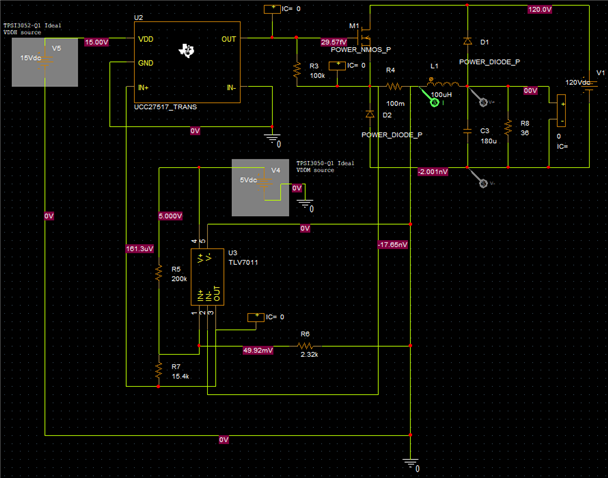
Other Parts Discussed in Thread: TPSI3052-Q1
Hi Team,
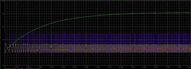
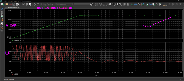
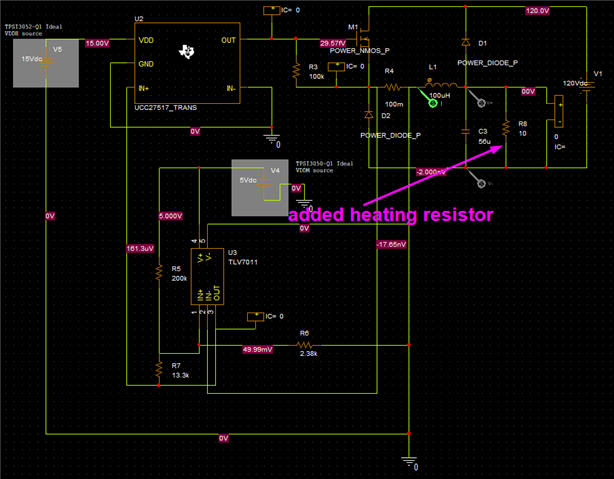
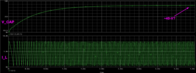
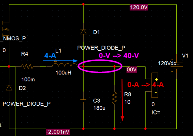
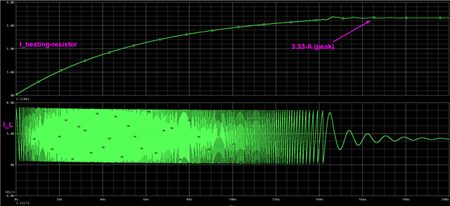
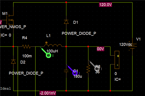
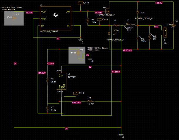
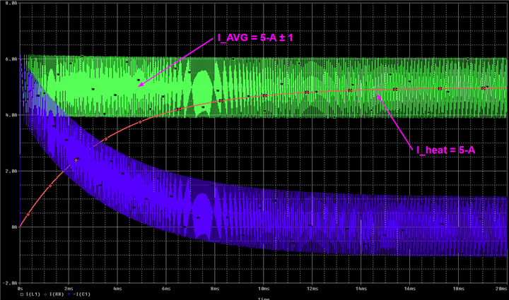
Is it suitable that i put a heating resistor between V_Cap and -HV for battery pre-heating?
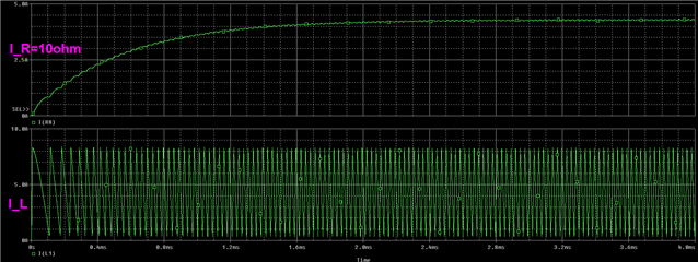
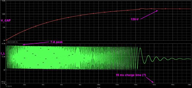
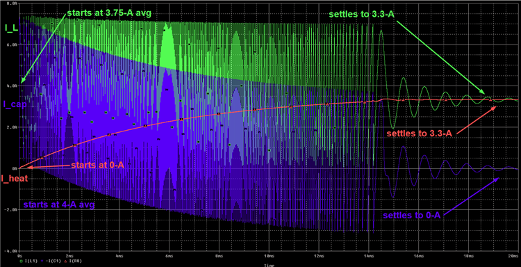
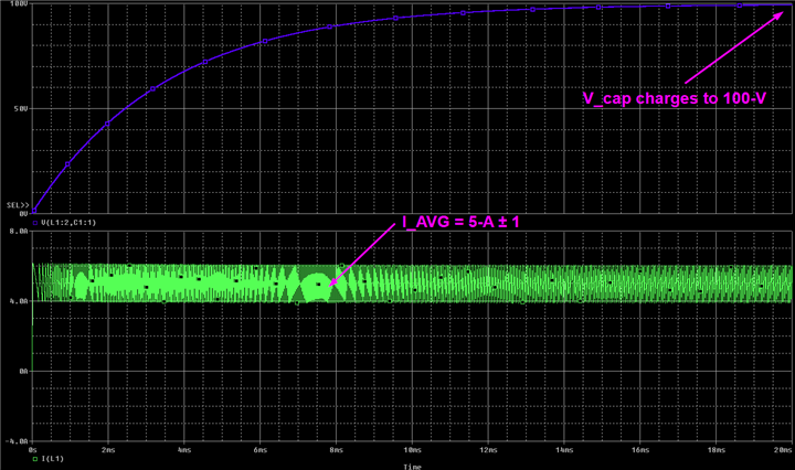
Will the switching frequency too low to keep a constant current?
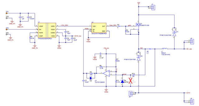
The battery voltage around 120V and output current for heater around 7A
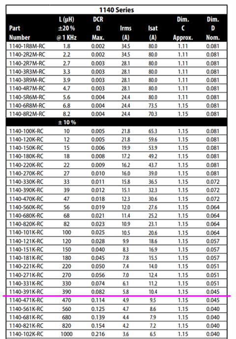
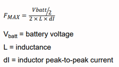
if it works, how can i choose the inductor?
Thank you