This thread has been locked.

If you have a related question, please click the "Ask a related question" button in the top right corner. The newly created question will be automatically linked to this question.

TPS7A54EVM-031: Multiple accuracy statments in the Datasheet and performance is not in line with them

Part Number: TPS7A54EVM-031

I am testing the achievable accuracy of this regulator for powering sensitive parallel optical transceivers. The regulator datasheet states multiple accuracies

  • Page 5: 0.75% for VIN between 1.4 V and 6.5 V
  • Page 5: 0.5% for VIN = 1.1 V with VBIAS between 3 V and 6.5 V
  • Page 16: "This device achieves a maximum of 1% output voltage accuracy

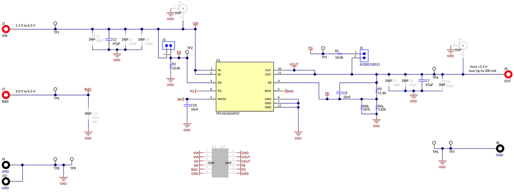
I am using the TPS7A54EVM-031 with Vin = 5 V aiming to get Vout = 3.3 V. For the feedback voltage divider, I have replaced R3 and R4 with the same size resistors with 0.1% tolerance as the following:

  • R3 = 11.8 kΩ
  • R4 = 3.776 kΩ (which is made of two resistors 3.83||2670)

Using different output accuracy calculation methods including the suggested method in this document by TI I find that output voltage should be:

  • 3.279 V to 3.322 V for regulator accuracy of 0.5%
  • 3.270 V to 3.330 V for regulator accuracy of 0.75%

However, conducting multiple measurements with a load current of 0A or 300mA using different instruments, including SDA816Zi-A oscilloscope with PP007-WR and DAQ6510 multimeter, to measure at points close to the IC showed that Vout = 3.330 V.

Can you please help me answer the below questions:

  1. What is the 1% accuracy mentioned on page 16? Is that the actual achievable accuracy? If so, then the measure Vout = 3.330 V is within regulator specifications
  2. The accuracy of 0.5% stated on page 5 requires powering the bias pin and works for low Vin and Vout. Does that mean that there is no way to achieve it for Vin =5 V and Vout = 3.3 V without powering the bias pin? Is there a recommended voltage to power the bias pin to get this accuracy for Vin = 5 V and Vout = 3.3 V?
  3. The measured Vout = 3.330 V is sitting right at the upper edge of the achievable Vout for regulator accuracy of 0.75% using the current configuration. should I then accept that the the achievable accuracy will be 0.75% and can't guarantee it to become 0.5%?

Kind regards
Nick

  • Hi Nick,

    Hope you are doing well and thank you for this question. Yes, 1% is the achievable accuracy of this device as stated on page 16. Yes, your measured voltage is within the rated accuracy range which is great. 

    2. Yes, the bias volage is required to get the stability and I would stick to the range shown in the data sheet as this is how the spec was captured. (3-V - 6.5-V). This is because the Bias rail is powering the charge pump and allows the input to charge other internals of the LDO allowing for more accuracy. 

    3. I would say that if you are outside the conditions of the data sheet for the 0.5% accuracy then I would not expect it to have this accuracy. 

    Please let me know if you have any further questions and I would be happy to help. 

  • Thank you for your reply Josh. To put this to bed I need confirmation that if I operate to the conditions of the datasheet for the 0.75% accuracy then it is achievable please. Is it?

    If it is, then I believe my above-detailed setup does operate to the conditions of the datasheet for the 0.75%, including leaving the Bias pin floating, yet the delivered Vout = 3.330V is too close to failing to achieve the 0.75%. That is because 3.330V is at the top edge of the voltage range achievable at 0.75% accuracy, which is (3.270 V to 3.330 V).

    Any suggestions on where my setup went wrong please? or is it just my luck that this very evaluation board is sitting at the top edge of the accuracy range?

  • Hi Nick,

    If you operate in the condition of the data sheet for 0.75% accuracy, then it is achievable. Please note that the data sheet states that it doesn't include the tolerances of the resistors. 

    If you are getting 0.75% accuracy with leaving the bias pin floating and it is corresponding with the data sheet, then great.

    Can I take a look at your schematic? It's much easier to diagnose it than a description.  I don't think you will have an issue though if you are running these tests and confirming accuracy on your end. 

    Thank you,

    Josh Nachassi 

  • Hello Josh,

    See my schematic below, which is the TPS7A54EVM-031 schematic after replacing:

    • R3 11.8k 1% tolerance with R3 11.8k 0.1% tolerance
    • R4 3.74k 1% tolerance with R4a and R4b in parallel, where R4a and R4b are 3.83k and 267k respectively and both have 0.1% tolerance

    Note that:

    • Vin is tied to a power source that supplies a current of 2 A Max and a voltage of 5V
    • No load on the output
    • BIAS is left floating

    Following my own calculations and the calculation method published at https://www.ti.com/lit/an/slva423/slva423.pdf, I find that this schematic should deliver:

    • Accuracy = 0.152% (resistors') + 0.75% (regulator's) = 0.902%
    • Vout = 3.270 V to 3.330 V

    Actual measured Vout = 3.330 using the mentioned high-accuracy devices.

    So is it just my luck that my very evaluation board is sitting at the top edge of the accuracy range? or did I do something wrong please?


  • Hi Nick,

    Thanks for sharing. There is obviously nothing wrong with the EVM schematic and your input voltage and output voltage are within a normal operating range so I would assume that nothing is going wrong. What if instead of two resistors in parallel for R2 you use 1 resistor to get it more accurate? Or maybe you can adjust your resistors accordingly to get the exact 3.3-V you are looking for. These are suggestions for you but overall, there is no systemic issue.

    Please let me know if you have any further questions and I would be happy to help. 

    Thank you,

    Josh Nachassi

  • Hello Josh,

    I have tested another evaluation board and confirmed that I can achieve 0.75% accuracy. it looks like the first board was simply performing at the very edge of the 0.75% tolerance after all