This thread has been locked.

If you have a related question, please click the "Ask a related question" button in the top right corner. The newly created question will be automatically linked to this question.

LM25149-Q1EVM-2100: Behavior of short circuit protection

Part Number: LM25149-Q1EVM-2100

Hi team,

My customer is using our LM25149-Q1EVM and do the short circuit protection test by the e-load.

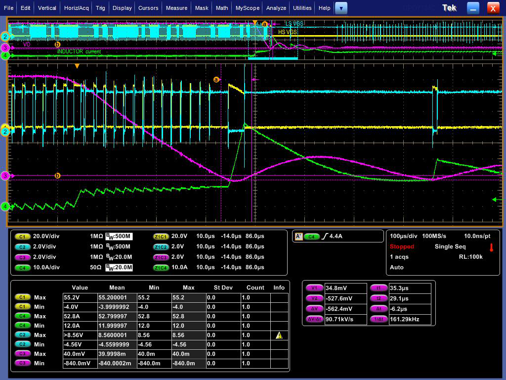
for the delay time of ISNS+ is about 65ns, the current limit threshold is 60mV and we use 30V as input,

the IL peak would be 14.86A as the calculation.

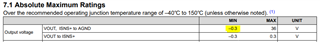
how to determine the Io peak is reasonable and suitable or not?

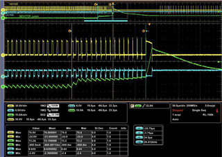
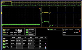
We measured the output current peak would increase to 48A, and the peak occur at 150ms after the short occurred.

Is the spike current caused by the power from output cap?

Thanks,

Gilbert.  

  • Hi Gilbert,

    You would have to measure inductor current with a current loop to see the current limit behavior.

    The output current will be supplied by the output capacitor yes.

    It looks like after that spike, your average output current is ~15A, and the peak inductor current would be higher.

    Check your inductor, and the inductance change vs DC current.

    Hope this helps,

    -Orlando

  • this capture is when the short occurred.

    ch1 and ch2 are high low side gate,

    ch4 is inductor current

    what will cause the gate signal like fully turn on, the inductor current is spiking at this time.

    as the block diagram, the current limit function might be more high level than the voltage control am I correct?

    so the gate control signal might not cause by the output voltage drop.

    could you kindly comment this capture? 

  • Hi Gilbert,

    Can you check VOUT during this?

    I suspect VOUT has gone to 0V or even negative, when LO is ON the inductor current should be sloped downward based on VOUT/L, however it flattens.

    When the VOUT has gone below -0.3V, the current limiting cannot work.

    VOUT going negative is usually due the the short being inductive through wires or so, reducing inductance in the short will reduce VOUT risk of going negative.

    Hope this helps,

    -Orlando

  • Hi Orlando

    The Vout will drop to -0.8V when the short occured. 

    It seems that the drop of vout under -0.3V also related to the short slope. 

    If not reduce the  inductive through wires, Is the first short peak current acceptable in the case of MOS SOA pass?

    Condition:Vin=50V, Vo=12.5V, f=600khz, 

  • Hi Chang,

    Yes it is something to worry about with the MOSFET, however the pulse is short lived, 200-300us.

    The FET datasheet says its supports a continuous current of 60A, and a pulsed current of 240A, although it does not specify anything about the pulse timing.

    https://www.infineon.com/dgdl/Infineon-IAUC60N04S6L039-DataSheet-v01_00-EN.pdf?fileId=5546d4626afcd350016b1c511cb70df6 

    You can use a schottky diode from GND to VOUT to to limit the negative VOUT.

    Hope this helps,

    -Orlando

  • Hi Orlando 

    When the VOUT has gone below -0.3V, the current limiting cannot work.

    ==>May I know where the -0.3V require on datasheet?  I try to reduce through wires  in the short test, but not improve.

  • Hi Chang,

    It is in the ABSMAX table, section 7.1.

    Are you able to do the short test on the board without using wires? Just a metal contact on the VOUT and GND to minimize inductance, like the tip of a screwdriver.

    Otherwise you will have to use a schottky diode to limit VOUT negative transient.

    -Orlando