This thread has been locked.
If you have a related question, please click the "Ask a related question" button in the top right corner. The newly created question will be automatically linked to this question.
Hi everyone,
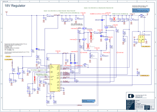
We have a design that uses the LM5175 and are seeing issues with output regulation.
It is an 18V/5A design. 8 to 6V input.
With no-load in boost mode it operates nicely at 18V, on load the output drops volts, more at lower VIN.
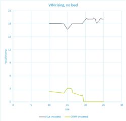
With no-load when VIN transitions into the buck-boost region ~15V, when the VIN drops the output is locked to VIN +1.5V.
With no-load in boost it sits are 19V, on load it regualtes to around 17.5 to 17.75V.
Yes compared to the EVM board we are missing capacitors on ISNS, BIAS and VOSNS. To check I have removed these from teh EVM and it made little difference.
Also, the COMP pin clips to 3V during teh buck-boost region and it only operates in buck mode with COMP pin 0V. Why could this be?
Any thoughts or support in helping with this issue will be apprecidated.
Regards,
Humphrey
Hello Humphrey,
For testing I would remove first the 10 ohm gate resistors and replace them with 0 ohm.
At the first glance, the schematic seems to be ok, but I did not find the time to fill in the quickstart calculator today: Here you can find it, to check if there is any obvious change necessary in the values of the external components: LM5175QUICKSTART-CALC Calculation tool | TI.com
As you seem to have an EVM available, I would recommend to take the components you are using onto the EVM to exclude layout.
Best regards,
Brigitte
Hello Brigitte,
Thank you for your reply and your recommendation on the gate resistors. I will look to alter these soon.
I have put the numbers into the calcuation sheet and have been looking at the COMP components, I believe that the schematic values were calculated using the quickstart sheet previously. Though I note that the values calaculated by the webbench are quite different.
Schematic values, 2.7k and 15nF. In the quickstart sheet this says the crossover is, at Vin-min, 7.9kHz (62 degrees phase margin)
I have recalculated from the datasheet 3.5k and 12nF. This gives crossover, at Vin-min, 10.6kHz (54 degrees)
But the webbench uses 8.9k and 8.2nF. These values in the quickstart sheet gives, at Vin-min, 41.9kHz (-21 degrees). This is a concern.
From the datasheet the fRHP = 37.6kHz. So the webebnch seems to place teh crossover above the fRHP figure, or at least very close to it when considering VIN-min. Given the datasheet recommendation of fRHP/3 for the crossover I am expecting <12.5kHz which both the top two solutions provide.
Along with the 2.7k/15nF I have testee our board with 10k/10nF which is much closer to the webbench. This did not yeild any noticable change in behaviour.
The biggest change in behaviour came from changing the Cslope down to 68pF. Where the load regulation improved, but the regualtor getting stuck in the buck-boost transition region still happpens.
If you have any thoguhts or recommendations based on this it will be appreciated.
Regards,
Humphrey
Hello Humphrey,
The converter getting stuck in buck-boost is strange. Can you please measure VISNS and VOSNS when this happens? Possibly adding a small cap in the pF range at these pins might help.
Can you please measure the input and output voltage in reference to the GND pins of the device when this happens?
Seeing some switching activity might help as well what is going on there.
As Webench and the quickstart calculator are not using exactly the same formulas, it is normal that the results are somewhat different. At the end both of them will be somewhat off reality on the board as none includes parasitics. So tweaking the compensation on the board is necessary.
68nF is a really big slope. I would try to stay at or above 100nF.
Best regards,
Brigitte
Hi Brigitte,
Many thanks for your advice, I went through a process of adding caps to VISNS and VOSNS, adjusting the CS filter and ISNS resistance.
The fault was the CS resistor, the order number for the part is an 80m Ohm resistor not a 8m Ohm one. I have some of the right parts on order, but swapped it for an 10m Ohm and it now works as expected. On 1A load output is 18V from 10V to 20V, good as a first test!
Regards,
Humphrey